
More Information
Submitted: January 24, 2026 | Approved: February 02, 2026 | Published: February 03, 2026
How to cite this article: Cervellieri A. Evaluation of the Mechanical Behavior of Intradosal Plating Brick and Cement Joists with UHTSS Galvanized Steel Fiber Fabrics and Thixotropic Structural Mineral Geomortar Certified EN 1504 for Civil Applications. Ann Civil Environ Eng. 2026; 10(1): 001-008. Available from:
https://dx.doi.org/10.29328/journal.acee.1001086
DOI: 10.29328/journal.acee.1001086
Copyright license: © Cervellieri A. This is an open access article distributed under the Creative Commons Attribution License, which permits unrestricted use, distribution, and reproduction in any medium, provided the original work is properly cited.
Keywords: Comsol multiphysics; Forecasting method; FRCM; Digital image correlation

Evaluation of the Mechanical Behavior of Intradosal Plating Brick and Cement Joists with UHTSS Galvanized Steel Fiber Fabrics and Thixotropic Structural Mineral Geomortar Certified EN 1504 for Civil Applications
Alice Cervellieri*
Honours Professor, The Institute for Basic Research, USA
*Address for Correspondence: Alice Cervellieri, Honours Professor, The Institute for Basic Research, USA, Email: [email protected]
The research project aims to provide an overview of the use of the Digital Image Correlation (DIC) methodology, in relation to composite materials, through the exposure of joists made during the research activity and from the results obtained from the displacement and deformation fields of a region of interest (abbreviation ROI, from “region of interest”) of a joist subjected to a flexural test by means of a image processing. This study is based on an Research Activity made at the Material Testing Laboratory - University of San Marino in 2016 based on flexure tests on brick and cement joists with intradosal plating with UHTSS galvanized steel fiber fabrics and thixotropic structural mineral geomortar certified EN 1504, followed by the application of the DIC (Digital Image Correlation) method with the use of an opensource program for MATLAB for the correlation of 2D digital images in association with the Comsol Multiphysics software have allowed the achievement of this goal. The final part of this research project concerns the design and performance of flexure tests, to investigate the accuracy of the DIC technique for the case of intradosal brick and cement joists with intradosal plating with UHTSS galvanized steel fiber fabrics and thixotropic structural mineral geomortar certified EN 1504 for Civil Applications, and in this phase, the validation of the results obtained by the DIC method applied becomes useful. The mechanical characterization focused on three-point bending tests, with varying support spans to investigate the flexural properties and failure mechanisms. The variations in support span provided insights into the transition from fiber-dominated to matrix-dominated failure, offering a comprehensive understanding of the structural response under different loading conditions.
In recent years in the field of civil engineering, scientific research has focused on the study of techniques and materials aimed at the recovery and reinforcement of existing building structures [1-9]. This has led to the use of innovative materials, such as fibre-reinforced composite materials (FRP), which are constantly evolving. It is therefore of current interest to investigate and observe the behavior and mechanical properties of these materials in the long term. This is possible through their subjection to tests and trials, performed with various measuring instruments, e.g., strain gauges and potentiometers. As an alternative to traditional measurement methods, in the 80s, a new technique was developed by researchers at the University of South Carolina, consisting of the processing and comparison of digital images, called “DIGITAL IMAGE CORRELATION” (DIC) [10-14]. Digital image correlation is a non-contact optical method for measuring displacement, strain, and vibration in objects or materials subjected to applied forces. This method compares two images, before and after warping or displacement, captured in white light with a digital camera (for a 2D DIC) or two digital cameras (for a 3D DIC) arranged at an angle (stereoscopic system). Subsequently, there is the use of an image processing program of your choice. With the use of efficient and valid calculation algorithms, the software correlates the two images and determines the displacements and, therefore, the deformations or vibrations in the two-dimensional and three-dimensional field. In this context, my present work is inserted, which analyzes the previous results obtained with an internship activity carried out at the Materials Testing laboratory of the University of Engineering of San Marino in 2016. The experiments consisted of flexure tests on brick and cement joists with intradosal plating with UHTSS galvanized steel fiber fabrics and thixotropic structural mineral geomortar certified EN 1504, followed by the application of the DIC method with the use of an open-source program for MATLAB for the correlation of 2D digital images. My paper aims to provide an overview of the use of the Digital Image Correlation (DIC) methodology, in relation to composite materials, through the exposure of the joists I have made and the results obtained. The main purpose of the DIC technique is to obtain the displacement and strain fields of a region of interest (abbr. ROI, from “region of interest”) of a joist subjected to a bending test. DIC uses an image processing technique in a specific attempt to solve this problem. Basically, the images of the specimen are taken as it deforms; these images become “input” for a DIC program. The idea is to somehow obtain a one-to-one correspondence between the material points of the reference image (the initial non-deformed photo) and the current configuration (the subsequent deformed photos). The DIC does this by taking small sub-sections of the reference image, called “subsets”, and determining their respective locations in the current configuration. For each subset, we get the displacement and strain information caused by the transformation and use it to match the position of the subset in the current configuration. Comsol Multiphysics permit to evaluate the results of the DIC measurement applied to optimize the best practices in the production of FRCM systems and predict mechanical strength, durability, and compatibility of reinforcements, avoiding the collapse of the historic masonry. Integration with artificial intelligence and quantum algorithms allows for the precise identification of fatigue crack tips, improving structural safety [15].
The result is a grid containing the displacement and strain information relative to the reference configuration, also known as Lagrangian displacements/deformations. The displacement/strain fields can also be reduced or interpolated to form a “continuous” displacement/strain field.
The objective of this Research article is to evaluate how production techniques affect the tensile strength, compression, elastic modulus, and adhesion behavior of FRCM composites.
- Materials considered:
- Continuous basalt fibers are woven in a mesh.
- Inorganic matrices (lime or cement) for FRCM systems.
- Coating and prepreg of the fibers, where applicable.
Compared to existing literature, this research article presents the validation of DIC for the specific system studied. In particular, it was observed that the DIC method was particularly useful for the following advantages: the DIC method (Digital Image Correlation) used in the following research project has replaced the strain gauges and was used to fully monitor of the element subject to the test and determine so the diagram loads -deflection according to the Belgian standard NBN B15-239 and to the Japanese standard JSCE SF4 allowing the comparison with PBO-FRCM composites.
Digital Image Correlation (DIC) is a tactile optical technique that allows you to measure full-field deformations and displacements using digital images of objects before and after deformations. Its flexibility and precision offer various application possibilities in advanced technological and industrial sectors.
The most innovative applications are:
Structural and industrial monitoring
Detection of defects and cracks: Through 2D or 3D DIC, it is possible to identify microcracks or failure points in industrial, aerospace, and civil components without direct contact.
Material fatigue assessment: Integration with artificial intelligence and quantum algorithms allows for the precise identification of fatigue crack tips, improving structural safety.
Quality control testing: Precise measurements of deformations during mechanical tests to verify the conformity of components and materials.
Additive manufacturing and advanced materials
Validation of additive prototypes: The DIC allows for evaluating and analyzing deformations on objects made with additive techniques such as SLA, FDM, DLP, LMD, LOM, and EBM.
Optimization of production processes: Rapid and contactless measurement allows you to reduce time and costs during the experimentation phase of new materials and complex geometries.
Analysis on high-performance materials: Allows you to determine Young’s modulus and strain properties on advanced superalloys or composites by integrating calculations from individual tests.
Biomechanical and medical engineering
Biological tissue analysis: Applications in bone, muscle, and soft tissue studies to evaluate behavior under load and response to prostheses or medical devices.
3D reconstruction: Three-dimensional models of body or tissue with subpixel accuracy allow stress/strain assessments at a localized level.
Prevention of microstructural damage: Identification of critical regions in biometric implants or tests on artificial anatomical models.
Micro and nano-scale
Micro-mechanics of materials: The use of DIC associated with optical or electron microscopes allows analysis of deformations on a micro- or nanoscale.
Nanopatterning SEM-DIC: Use of nanoparticles as speckles for syudis in scanning electron microscopy, extending the accuracy of the technique to extremely small scales.
Innovative and Advanced Integration
Volumetric DIC (V-DIC): It is represented by a combination of computed axial tomography (CT), magnetic resonance imaging (MRI), or PET for internal body measurements or industrial components.
Correlation with numerical simulations: Coupling between DIC and FEM models for calibration and validation of simulations, reducing uncertainty and experimental iterations.
Algorithmic optimization: It consists of sub-pixel registration techniques and advanced filtering to improve accuracy, reduce noise, and speed up computation on large datasets.
Strategic Industrial Areas
Aerospace: It concerns the structural control of composite wings and fuselages, the evaluation of critical materials, and data collection during crash or vibration tests.
Automotive: Deformation analysis of metal and polymer components under dynamic loading, prototype validation, and molding processes.
Energy and infrastructure: It concerns the monitoring of turbines, bridges, dams, and structures subjected to cyclical or environmental stresses.
Flexure tests on brick and cement joists with intradosal plating with UHTSS galvanized steel fiber fabrics and thixotropic structural mineral geomortar certified EN 1504
The experiments consisted of flexure tests on brick and cement joists with intradosal plating with UHTSS galvanized steel fiber fabrics and thixotropic structural mineral geomortar certified EN 1504.
The objective of the test is to identify the entire surface displacement field, so the captured photos must have a very high resolution. To this end, the surface of the joist must be made as homogeneous as possible; it is difficult, if not almost impossible, to distinguish the relative displacements between the surface points. For this reason, a method is used to create the necessary non-homogenizing contrast between the aforementioned points. To have an optimal speckle pattern, various methods are used for its creation; for example, an electronic interferometer can be used. In my case, I decided to apply a layer of white paint, followed by a spray of black paint, to create a pattern of dark spots. The two layers together form what is called a “speckle pattern”. You have to pay attention to how the speckled pattern is made, as the number of speckles should be neither excessive nor too small. Otherwise, in the first case, there will be an overlap of the subsets, due to a background that is too dark; in the second case, however, it will not be possible to find the deformation field on the entire surface.
Laboratory activities
Preparation and preparation of formwork: About the preparation of the formwork, it was ascertained that they are well fixed and have sufficient rigidity to withstand the thrust of the concrete during the installation phase and subsequent compaction of the castings without undergoing significant deformations. All precautions must also be taken to ensure a perfect seal of the formwork to prevent the excessive fluidity of the concrete from causing the appearance of defects that are not only aesthetic for the concrete structure.
Surface aesthetics: During the research activity, it was ensured that the surface of the formwork was not polluted by traces of dirt or soil, in order to prevent the aesthetic quality of the artifact from being compromised. In this way, it was avoided to alternate new boards with those already used.
Disarming: To avoid the appearance of unsightly stains on the surface of the concrete, it was necessary to apply just enough release agent to ensure a homogeneous and complete covering of the surface of the formwork.
For 25/30 concrete, the following were used:
- 7.30 liters of water;
- Half a 25 kg bag of cement
- 42 litres of inert mixture.
Execution of the experimental test: The experiments consisted of flexure tests on brick and cement joists with intradosal plating with UHTSS galvanized steel fiber fabrics and thixotropic structural mineral geomortar certified EN 1504. The compound described above was placed in the concrete mixer for a maximum of 20 minutes, the casting inside the formworks, and a manual vibration was carried out by striking the surface with rubber hammers to promote the surface of air bubbles and avoid the segregation of the coarser material. Finally, the surface was brushed with grout, a mixture of water and cement, to level the surface. After pouring, it is essential to ensure that the mix matures correctly, developing the characteristic strength. For this phenomenon to occur, it is necessary to protect and care for the conglomerate so that the environmental conditions do not affect the regular maturation of the casting. The stripping operations of the castings can only begin when the concrete has reached a strength such as to make it self-supporting and not able to suffer damage due to the lack of formwork. The development of conventional resistance takes place at 28 days, and before this time, no operating loads have been applied. In the case of these joists, not all the props were removed at the same time, but some were left in place, especially in the neuralgic points of the structure. The concrete was protected from evaporation with waterproof films. After two weeks, we formed the concrete blocks to allow the insertion of the slab of reinforcing material. We have mounted the classic hinges of 11.5x11.5 cm with a total footprint of 8 cm. We connected the two concrete blocks after diagonal drilling and treated the surface to make it rough.
To facilitate the adhesion of the mortar, a grid was created with the hose, in which the grooves have a depth of 3 mm. During this research activity, the mortar used consisted of one part water and five parts. It was positioned and spread after wetting the surface until it reached a thickness of 4 mm. Finally, the steel fiber was placed, to have an anchor length of 30 cm, and covered with an additional layer of 4 mm mortar. A second family of blocks was then created in which the anchor length was varied by 40 cm. Similarly, a 4 mm layer of mortar was first placed, then a layer of reinforcing material, and finally a 4 mm layer of mortar.
During this research activity, a bending test was carried out on all reinforced joists.
In the three-point test, the specimens are constrained with two supports in the lower part and loaded in the center by a wedge integral with the moving crossbar of the machine.
The flexure test has the following advantages:
- Easy to grip and execute,
- Simple geometry of the specimen, generally with a rectangular section,
- Larger displacements for more precise measurement.
The specimen geometry in the following figure is described by the following parameters:
- l = useful length (the part between the supports),
- b = width of the section,
- h = height of the section.
Materials cosidered
The research activity consisted of the study of brick and cement joists with intradosal plating with UHTSS galvanized steel fiber fabrics and thixotropic structural mineral geomortar certified EN 1504, followed by the application of the DIC method with the use of an open-source program for MATLAB for the correlation of 2D digital images. To correctly model a specimen in cement mortar with the Comsol Multiphysics Software, it was necessary to enter a series of data relating to both the properties of the material and the condition of the model. Cement mortar is characterized by a series of main mechanical and thermal parameters that have been reported in the following Tables 1,2.
| Table 1: Mechanical parameter. | |
| Density (ρ) | 2000–2200 [kg/m³] |
| Modulus of elasticity (E) | 10–25 [Gpa] |
| Poisson's coefficient (ν) | 0.2–0.25 |
| Compressive strength (σc) | 10–30 [Mpa] |
| Table 2: Thermal parameter. | |
| Thermal conductivity (k) | 1.0–1.5 [W/(m·K)] |
| Specific Heat Capacity (Cp) | 900–1000 [J/(kg·K)] |
Thermo-mechanical phenomena were evaluated in the simulation by compiling the mechanical and possibly thermal properties.
To evaluate the strength qualities of the concrete, the elements specified in the previous Chapters have been analyzed and compared with the case study reported in the article [15], in which there were studied shear reinforced beam was studied using a mesh made of PBO fibre (p-Phenylene Benzobis Oxazole) Ruredil X Mesh Gold and mineral mortar Ruredil X Mesh M750. The main mechanical properties of PBO fibers, evaluated according to the manufacturer, are collected in Table 3. In Table 3 are reported the mechanical properties of PBO fibers, and the mechanical properties of the PBOFRCM system, adopted from the ACI549.4R-13.
| Table 3: Mechanical and geometrical parameters of the FRCM strengthening materials [16]. | ||||
| Tensile strength ffz [MPa] | Young modulus Ef [GPa] | Ultimate tensile strain ɛ [%] | Thickness of composite [mm] | |
| PBO fibre mesh | 5800 | 270 | 2.15 | 0.0455 |
| PBO-FRCM system | 1664 | 137 | 1.76 | - |
The beam was strengthened with one layer of PBO mesh with associated cement mortar, discontinuously with 150 mm wide FRCM strips with a spacing of 100 mm [15]. FRCM strengthening was applied on both sides and the bottom of the web. During this phase, a strengthening configuration called U-wrapped is used. Before strengthening, the surface of the beam was cleaned of laitance, dusted, and washed. The corners of the beam were rounded in the domain where the outer composite stirrups were applied, in order to prevent the local stress concentration. The surfaces of the web were saturated with water for 15 min before placing the FRCM strips. The first layer of the mortar was applied, and fabric strips were placed. The PBO mesh was applied after application of the first mortar layer and then pressed slightly into the mortar. In the case of anchoring, 20 × 20 mm cuts were made under the slab. After shear strengthening, the ends of the PBO strips were wound on a GFRP bar and glued in a cut under the shelf.
Production methodology
Description of manufacturing processes and civil engineering processes: In the context of a research or development project on the use of composite materials for structural reinforcement, this research activity documents the effects of production processes on material properties in a structured way. For fiber-reinforced cementitious matrix (FRCM) systems, this project includes experimental data, manufacturing process observations, mechanical property analysis, and comparative evaluations between materials and manufacturing methods:
- Prepreg and lamination: Impregnation of the fibers with partially cured resins or matrices.
- Automatic fiber deposition (AFP/ATL): Controlled orientation, management of curvatures and overlaps (tow overlap/gap).
- Manual positioning and compaction for FRCM systems on wall substrates.
- Operating conditions: Temperature and humidity of the matrix. Deposition speed and pressure.
- Optimal parameters for the manual positioning and compaction of the FRCM system on wall substrates
Types of tests
This research project, in addition to the objectives expressed above, includes quantitative and qualitative results of mechanical tests:
- Tensile test: Evaluation of the maximum load and elongation at break of the fibers and the complete composite. Compression and flexure tests of the FRCM matrix and samples. Direct Shear Test (DSS):
- Measurement of stress transfer capacity.
- Modulation of production parameters: Analysis of the effects of density, thickness, and orientation of fibers on mechanical behavior.
- Visual and ultrasonic monitoring: Identification of defects such as voids, fiber buckling, or delaminations.
Flexure test
Depending on the standard to which reference is made for their execution, the flexure tests carried out on fiber-reinforced concretes can be of two types:
According to the Belgian standard NBN B15-239 and according to the Japanese standard JSCE SF4, a four-point flexure test shall be performed on prismatic specimens having dimensions 150×150×600 mm. The standard shows the loading mode usually consisting of three- or four-point tests and the recording of the deformations in order to obtain the load-strain curve (P-δ). The parameters resulting from the test are:
The flexural strength at first crack and collapse;
Toughness of the material, i.e., the energy used to deform the specimen until collapse, as can be deduced from the total area subtended by the load-strain curve (P–δ);
Evaluation of post-cracking behavior, i.e., how fibers affect the ductility and energy absorption of concrete.
According to the Italian standard UNI 11039, on the other hand, the test must be conducted on beams of similar size but characterized by the presence of a notch in the mid-air of the lower edge.
In both cases, the flexural behavior is defined on the basis of a nominal tensile stress evaluated by assuming a linear elastic behavior of the specimen.
Load–displacement curves
The following figure illustrates the P-δ graph (i.e., of the load P applied as a function of the deflection δ in the centerline) of a flexure test performed on unnotched joists made of ordinary concrete (curve A) or fiber-reinforced concrete (curve B).
Failure mode evaluations
In this research activity, when the load that causes the initiation of a crack is reached, starting from the most tense edge (Pf), a sudden collapse is observed due to the rapid propagation of the lesion in the joist.
The deflection at the moment of the appearance of the first crack (δf) is slightly less (and almost coincident) than that which corresponds to the complete crack (δr) as occurs in a brittle material.
The introduction of fibers does not change the load Pf, nor the slope of the curve in the initial linear section.
From the value of the load Pf, in the hypotheses made, the flexural strength of the material (Rr) is obtained through the formula (1):
(1)
The addition of fibers does not significantly change the flexural strength of the concrete.
The behavior of the system, with or without fibers, up to cracking, continues to be governed by the behavior of the cement matrix. The fibers modify the post-cracking behavior of the system; the deformation δ’f, which corresponds to the first appearance of the first crack, is much lower than that δ’r, which occurs when the FRC is completely broken, as typically occurs in a ductile material.
In the flexure tests on non-notched specimens, since it is not possible to establish a priori the point at which the crack will form, the post-cracking behavior is characterized on the basis of two deflection values δ1 and δ2 shown in Figure 1. By way of example, in the JSCE SF4 standard, the deflections δ1 and δ2 are set at 1.5 and 3.0 mm, respectively. These deflection values correspond to values of the applied load P1 and P2 from which, by means of equation (2):
(2)
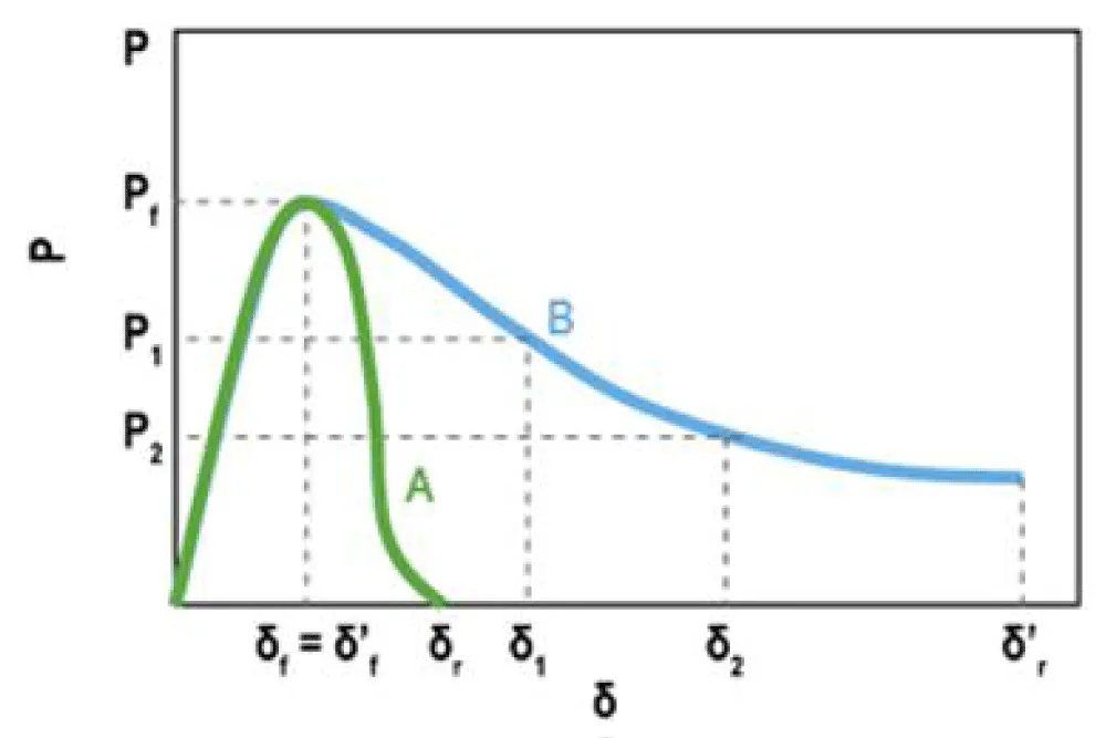
Figure 1: Load P - Deflection δ - Behavior of ordinary concrete (A) and fiber-reinforced concrete (B) in the flexure test for the application of a load P as a function of the bending δ [17].
From the calculations carried out, it is possible to derive the residual resistances R1 and R2.
These values, suitably modified, are used in the calculations to perform the checks at the service limit state and at the ultimate limit state.
Numerical and experimental validation
For the case described in [16], it is possible to examine the development of cracks and the distribution of deformations on the element considered a composite strip. During the test, diagonal cracks occurred past the PBO strips and developed between them (Figure 2).
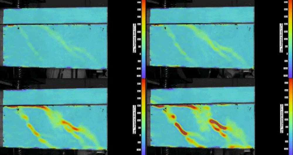
Figure 2: Image from DIC cameras showing the development of diagonal cracks in the beam during test [16].
The reference beam reached an ultimate load of 453.67 kN and failed in shear after the formation of the main diagonal crack on the shear span [16]. The strengthened beam also failed in shear with the formation of a main diagonal crack, and reached an ultimate load of 527.40 kN.
The model development was made based on the study of brick and cement joists with intradosal plating with UHTSS galvanized steel fiber fabrics and thixotropic structural mineral geomortar certified EN 1504, followed by the application of the DIC method with the use of an open-source program for MATLAB for the correlation of 2D digital images. For the correct realization of the model of brick and cement joists with intradosal plating with UHTSS galvanized steel fiber fabrics and thixotropic structural mineral geomortar certified EN 1504 with the Comsol Multiphysics Software, it was necessary to enter a series of data relating to both the properties of the material and the condition of the model. Cement mortar is characterized by a series of main mechanical parameters that have been reported in Comsol Multiphysics:
- Density (ρ): 2000–2200 [kg/m³]
- Modulus of elasticity (E): 10–25 [Gpa]
- Poisson’s coefficient (ν): 0.2–0.25
- Compressive strength (σc): 10–30 [Mpa]
The main thermal parameters that have been reported in Comsol Multiphysics are:
- Thermal conductivity (k): 1.0–1.5 [W/(m·K)]
- Specific Heat Capacity (Cp): 900–1000 [J/(kg·K)]
Thermo-mechanical phenomena were evaluated in the simulation by compiling the mechanical and possibly thermal properties, which are visible in Figure 3.
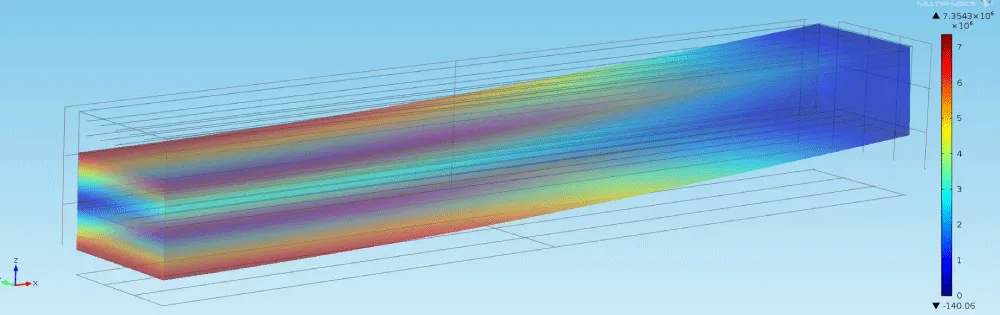
Figure 3: Specimen Fabrication with Comsol Software.
Revision and optimization process
Further consideration and analysis can be expressed with the use of COMSOL Multiphysics® software modelization, and are reported in Figure 3.
From this simulation is possible to predict:
- The influence of fiber orientation on the tensile behavior of FRCMs and the effects of overlaps or voids due to the ATL/AFP technique on the final elastic modulus and adhesion to the substrate.
- Evaluation of ductility and post-peak strength.
- Impacts of environmental and process conditions ("curing temperature", humidity) on early degradation or mechanical properties.
Quantitative results and outputs
From Table 4 and the previous consideration is possible to create Load-slip graphs and define the performance between different production methods and different compositions.
| Table 4: Mechanical value Mechanical value tables. | ||||
| Sample | Elastic modulus [GPa] |
Tensile strength [MPa] |
Compressive strength [MPa] | Process Notes |
| BFRP1 | 120 | 950 | 80 | Prepreg, Double pass controlled voltages |
| FRCM1 | 6 | 3,5 | 12 | Manual application, lime matrix |
This study aims to evaluate the mechanical behavior of basalt fiber-reinforced polymer (BFRP) laminates manufactured for Industrial Applications using two distinct processes: manual lay-up with polyester resin and vacuum infusion with vinylester resin, based on a research activity made at the Material Testing Laboratory, University of San Marino in 2016 based on flexure tests on brick and cement joints with UHTSS galvanized steel fiber fabrics and thixotropic structural mineral geomortar certified EN 1504. The research project aims to provide an overview of the use of the Digital Image Correlation (DIC) methodology, in relation to composite materials, through the exposure of joists made during the research activity and from the results obtained from the displacement and deformation fields of a region of interest (abbreviation ROI, from “region of interest”) of a joist subjected to a flexural test by means of a image processing. The application of the DIGITAL IMAGE CORRELATION (DIC) method is followed by the use of an open-source program for MATLAB for the correlation of 2D digital images, which, in association with the Comsol Multiphysics software (used in a third part of this project), has allowed the achievement of this goal. The laminates were fabricated at the Intermarine shipyard in the default location, which provided industrially relevant conditions. The second part of this research project concerns the design and performance of flexure tests, in order to investigate the accuracy of the DIC technique for the case of intradosal brick and cement joists with intradosal plating with UHTSS galvanized steel fiber fabrics and thixotropic structural mineral geomortar certified EN 1504 for Civil Applications. In this phase, the validation of the results obtained by the DIC method becomes useful. The mechanical characterization focused on three-point bending tests, with varying support spans to investigate the flexural properties and failure mechanisms. In conclusion, DIC applied to this particular case study stands out for its non-invasive, full-field, high-resolution measurement and for its versatility of application based on multi-scale, making it a technique of increasing importance for industrial, civil engineering, and technological research. Recent innovations include integration with artificial intelligence, volumetric techniques, and multi-scale analysis, enhancing the ability to identify complex material behaviors and optimize advanced manufacturing processes and products. Comsol Multiphysics permit to evaluate the results of the DIC measurement applied to optimize the best practices in the production of FRCM systems and predict mechanical strength, durability, and compatibility of reinforcements, avoiding the collapse of the historic masonry. Integration with artificial intelligence and quantum algorithms allows for the precise identification of fatigue crack tips, improving structural safety.
- Cervellieri A. Effects of pulling on chains in historic masonry buildings applied to the case study of the Basilica of St. Mary Major in Bologna. 6th International Conference on Multidisciplinary and Current Educational Research (ICMCER-2025). 13–14 March 2025.
- Cervellieri A. Optimization method for evaluating the effects of chain pulling in historic masonry buildings applied to the case study of the Basilica of St. Mary Major in Bologna. International Conference on Multidisciplinary and Current Educational Research (ICMCER-2025). 13–14 March 2025.
- Cervellieri A. Compatibility of strengthening interventions using composite materials in the conservation of towers and bell towers. Master’s degree thesis. University of Bologna, Civil Engineering degree program (LS-DM509). 2011.
- Cervellieri A. Compatibility of strengthening interventions using composite materials in the conservation of towers and bell towers and structural design. Simple; 2013. ISBN: 9788862598194.
- Bournas DA, Triantafillou TC. Strengthening of arches and vaults in heritage constructions by composite systems. International Symposium on Historic Constructions. Florence, Italy; 2016.
- International Conference on Structural Analysis, Modeling, and Reinforcement. Proceedings of the International Conference on Structural Analysis, Modeling, and Reinforcement. Florence, Italy; 7–9 June 2016. European Structural Engineering Network.
- International Conference on Composite Materials for Civil and Structural Applications. Proceedings of the International Conference on Composite Materials for Civil and Structural Applications. Florence, Italy; 2–4 November 2016. Composite Materials International Society. Available from: https://www.cmassociation.org
- de Lorenzo G, Prota A. Seismic upgrading of reinforced concrete frames with composite overlays. 3rd International Conference on Seismic Retrofitting. Athens, Greece; 2016.
- Valerio V. Instantaneity and long duration: vulnerability, damage, and reconstruction of cultural heritage in earthquake-prone Italy. Florence: Kunsthistorisches Institut in Florence, Max Planck Institute; 2019.
- Silva J, Yang T, Huang P. DIC-based vibration modal analysis of civil structures. Engineering Structures. 2025;295:115456.
- Reu P. Error assessment and spatial resolution in two-dimensional digital image correlation. Focus on measurement uncertainty and the influence of camera resolution and speckle size in 2D-DIC applications.
- Zhao X. Extrusion and particle flow analysis using stereo digital image correlation. Application of stereovision DIC to fluid–structure interaction and particle flow studies, validated against numerical simulations.
- Haldar A, et al. Pin-reinforced composites under compression analyzed using digital image correlation. Study of compressive behavior of pin-reinforced composites and proposal of scaling methodologies using 2D-DIC.
- Shazly T. Characterization of soft biomaterials using digital image correlation. Examination of strain measurement in heterogeneous soft tissues, with emphasis on subset tracking and out-of-plane motion effects in 2D-DIC.
- National Research Council of Italy. CNR-DT 215/2018. Guidelines for the design, execution, and quality control of static strengthening interventions using fiber-reinforced inorganic matrix (FRCM) composites. 2018. Available from: http://www.cnr.it
- ACI Committee 549. Guide to the design and construction of externally bonded fabric-reinforced cementitious matrix (FRCM) systems for repair and strengthening. American Concrete Institute.
- Belgian Bureau for Standardization. NBN B15-239: Methods for concrete testing. Brussels, Belgium; 2020.