
More Information
Submitted: July 17, 2025 | Approved: September 02, 2025 | Published: September 03, 2025
How to cite this article: Zi C, Menghan S, Chunhui Z, luyao H, Zailin Y. Seismic Analysis of Semi-rigid Frames using Skeleton Joints. Ann Civil Environ Eng. 2025; 9(1): 073-079. Available from:
https://dx.doi.org/10.29328/journal.acee.1001083
DOI: 10.29328/journal.acee.1001083
Copyright license: © 2025 Zi C, et al. This is an open access article distributed under the Creative Commons Attribution License, which permits unrestricted use, distribution, and reproduction in any medium, provided the original work is properly cited.
Keywords: Semi-rigid connection; Seismic performance; Finite element analysis; Seismic responce

Seismic Analysis of Semi-rigid Frames using Skeleton Joints
Cai Zi, Sun Menghan*, Zhang Chunhui, He luyao and Yang Zailin
School of Aerospace and Civil Engineering, Harbin Engineering University, Harbin 150006, China
*Address for Correspondence: Sun Menghan, School of Aerospace and Civil Engineering, Harbin Engineering University, Harbin 150006, China, Email: [email protected]
This study proposes a new type of flange-widened bone-type semi-rigid frame node, and takes a 4-story frame as an example, uses the finite element software Abaqus to analyze its seismic performance under different seismic waves, and compares it with the traditional rigid connection frame. The results show that the stiffness of the new node frame is slightly lower than that of the tradition rigid node frame, which reduces the horizontal displacement of each layer under the action of earthquake, optimizes the deformation capacity, and enhances the force performance and ductility, the maximun value of the base shear force is lower than that of the traditional rigid frame, which can effectively disperse and dissipate the seismic energy andimprove the overall stabitity of the structure; the elastic-plastic interlayer displacement angle is less than 1/50 under rare earthquakes, which meets the requirements of the specification and can achieve the goal of “no collapse in a large earthquake”. In addition, the node can effectively improve the safety and reliability of the structure in actual engineering.
Developing new types of prefabricated steel structure beam-column joints is the key to improving the seismic performance of structures and innovating construction modes [1]. Column connection nodes are an important part of steel frame structures, transmitting axial force, shear force, and bending moment in the structure. Their performance directly affects the safety and reliability of the overall steel structure [2]. According to European standards, steel structure beam-column joints can be divided into three types: rigid connection, hinged connection, and semi-rigid connection [3]. The rigid connection assumption ignores the deformation energy dissipation capacity of the node, which may lead to deviations in the prediction of the internal force distribution of the structure; while the hinge assumption underestimates the influence of the node stiffness, and the overall stability of the structure is not considered. A semi-rigid node is a connection form that allows limited rotation. It can transmit part of the bending moment and shear force, and dissipate energy through deformation. Its core feature is that the bending stiffness of the node is between the rigid connection (infinite stiffness) and the hinge connection (stiffness approaches zero).
In the earthquake damage investigation of the Northridge earthquake in the United States in 1994 and the Kobe earthquake in Japan in 1995, it was found that the steel frame with fully welded rigid connection nodes suffered large-scale brittle failure of the structure due to poor node ductility, large welding residual stress and welding heat-affected zone; while the semi-rigid connection steel frame had strong deformation and energy dissipation capacity, and the structure did not suffer brittle failure, which greatly reduced the damage to the building in the earthquake. Therefore, domestic and foreign scholars have carried out a lot of research on the research and development of prefabricated nodes [4-20].
Liu et al. proposed a new type of bolted truss column node, and obtained the failure mode, mechanism, and seismic performance of the node through experiments and finite element analysis. At the same time, the comparative analysis of the test results of the sliding connection and the anti-slip node showed that the sliding connection showed better ductility and energy dissipation capacity, but the ultimate bearing capacity was not significantly reduced, and most of the energy was dissipated from the sliding [4-5]. Wang Hao et al. (2022) proposed a fully bolted column-beam node of steel modular structure, and conducted pseudo-static tests on four different full-size joint specimens. The seismic performance of the existing nodes was evaluated by analyzing the failure mode, hysteresis curve, strength, stiffness, rotation capacity, ductility, and energy dissipation capacity of the joints [6]. Zheng, LQ (2022) proposed a new energy-absorbing assembled node with replaceable steel hinges and a prefabricated steel pipe confined core. The hysteresis loading verified that the new node has improved load-bearing, energy dissipation, and deformation capacity compared with the integral node. At the same time, the node can meet the design concept of plastic controllable [20].
At present, there are certain limitations in the research on the beam-column nodes of prefabricated steel structures. Most studies focus on the seismic performance of a single node, and there are few studies on the coordinated work of nodes and components and the seismic performance of the overall structure [21-29]. In actual structures, the interaction between nodes and components, such as beams and columns, is complex. The lack of research in this area affects the accurate evaluation of the seismic performance of the overall structure.
Therefore, this paper proposes a new type of bone-type semi-rigid node. For a 4-story frame, the new node frame is analyzed by the finite element software Abaqus. The base shear force, acceleration, displacement time history curve, and inter-story displacement angle data under the action of seismic waves in different directions are studied. The relevant indicators are calculated to see whether they meet the specified requirements, and compared with the frame structure of the same cross-section with rigid connection. The node frame has good seismic performance and can be applied to general finite element analysis software, providing a theoretical basis for engineering design and seismic evaluation.
Node construction model
The flange widening bone node is composed of an H-shaped steel column, expanded flange bone beam, end plate, and bolts. As shown in the figure. Steel column, beam, and end plate are all made of Q235 steel, and bolts are made of 10.9 grade M16 high-strength bolts. Expanded flange bone beam and end plate can be welded and prefabricated in the factory, and the end plate and H-shaped steel column flange are connected by high-strength bolts and gaskets. Expanded flange end plate bone node can be used for the assembly of conventional I-shaped steel bars and box-shaped steel bars. It has a simple structure, convenient construction, high stiffness and strength, and can maintain good bending bearing capacity under earthquake action. The various components of the node can be prefabricated in the factory and directly transported to the construction site, which improves construction efficiency and reduces construction costs (Figure 1).
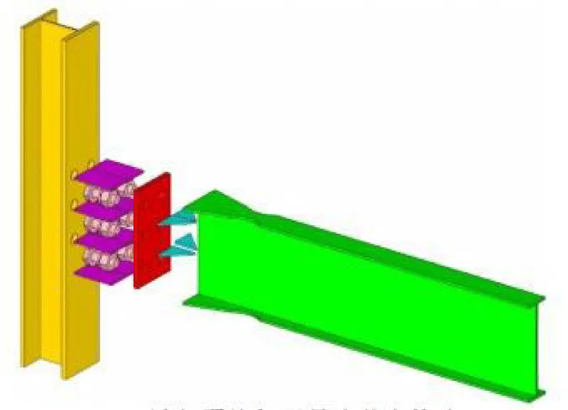
Figure 1: Geometric construction diagram of flange flange-widened bone node.
Frame construction model
Two frame models (Figure 2) are created using ABAQUS finite element software: J1 and J2. J1 is a beam-column welded frame, and J2 is a beam-column connection using a flange widening bone node. Both beams and columns are made of Q235B hot-rolled H-shaped steel; the cross section of the steel column is WH300×300×21×24, the cross section of the main beam is WH480×150×12×18, and the cross section of the secondary beam is HN400×200×8×13. The thickness of the floor slab is selected as 120mm. The seismic fortification intensity is 8 degrees, the basic earthquake acceleration is 0.5g, the second type of site category, and the earthquake period is 0.45s (Figure 3).
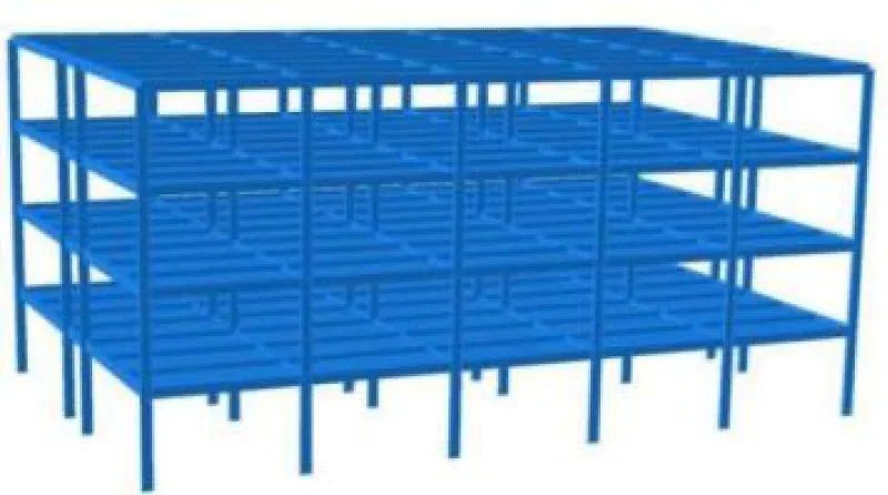
Figure 2: Frame structure model.
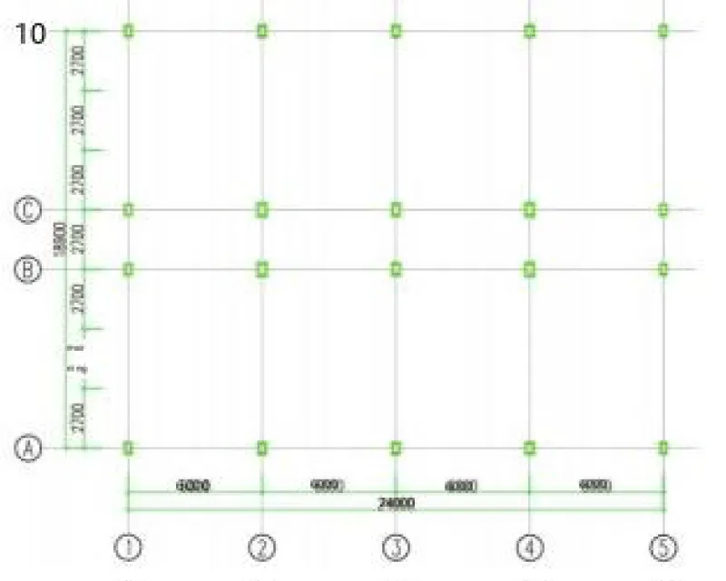
Figure 3: Frame structure plan.
Simplified beam-column node
In order to speed up the calculation rate, beam elements are used for the beams and columns of the frame. Considering the Von-Mises yield criterion and the bilinear kinematic hardening constitutive model, the elastic modulus of Q235 steel is 2.06×10⁵ MPa, and the Poisson’s ratio is 0.3.
Node connection simulates semi-rigid and rigid connections by creating line features between the beam-column nodes of the model [30], assigning the connection section type to hinge, and using nonlinear hinges to simulate the rotational stiffness of semi-rigid nodes. When defining the behavior of the hinge, you can enter the moment-rotation curve value of the semi-rigid solid node for the elastic option. When establishing a connection at a beam-column node, the node spring element uses the coordinate system moment direction along the positive x-axis to fix the translational degrees of freedom of the beam in the y and z directions to prevent deflection during loading.
To study the seismic capacity of the flange-widened dog-bone node frame, it is necessary to ensure the accuracy of the simplified model. Establish a solid portal frame model (Figure 4) and a simplified portal frame model (Figure 5). The frame solid model and the frame simplified model are subjected to unidirectional displacement loading [31]. The unidirectional loading was applied to the interlayer displacement angle of 0.1 rad, and the numerical simulation results were compared. It can be concluded that under the same loading conditions, the load-displacement curves calculated by the simplified node model and the solid model are in good agreement. Under the unidirectional displacement loading condition, the ultimate load of the solid model is 324.027 kN, and that of the simplified model is 322.375 kN, with a difference of 0.5%, and a high degree of agreement. This simplified method can effectively simulate the mechanical properties of the node (Figure 6).
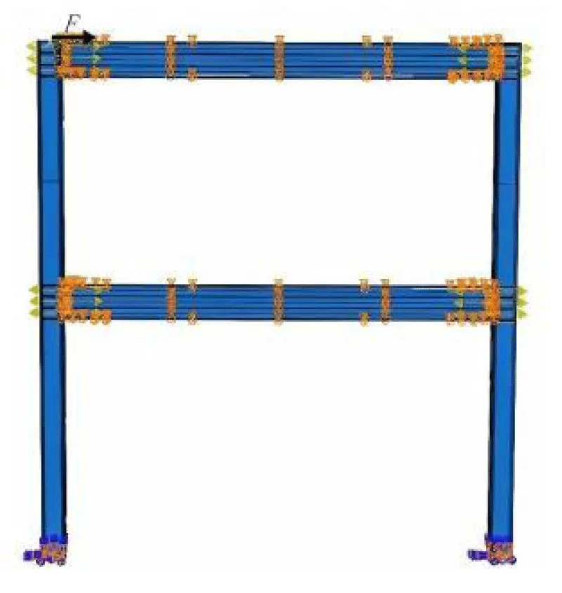
Figure 4: Portal frame solid model.
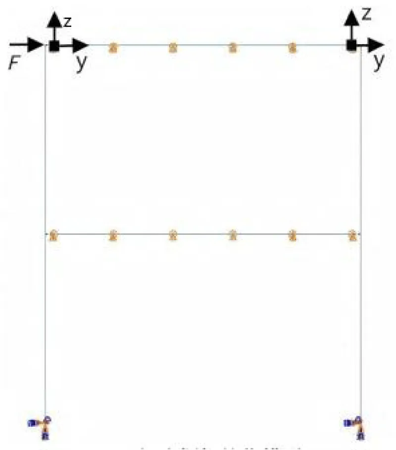
Figure 5: Simplified model of portal frame.
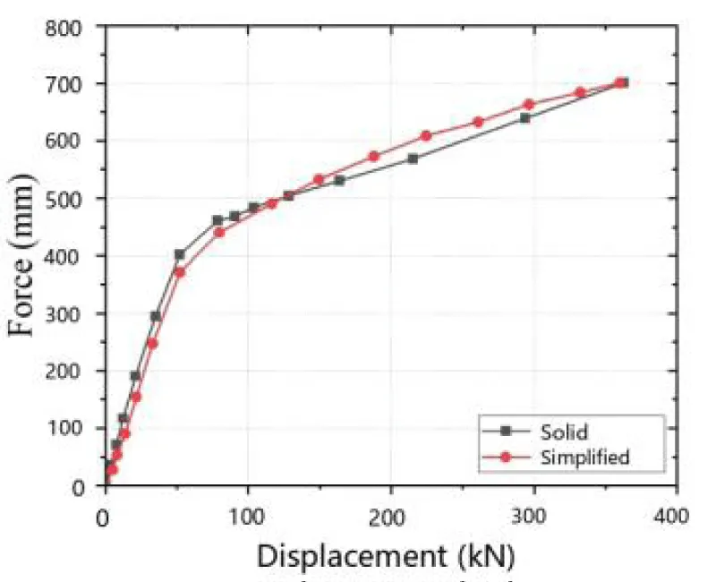
Figure 6: Comparison of load-displacement curves.
Finite element parameter setting and modal analysis
A total of 10 vibration modes of the structure are calculated in the response spectrum analysis, and the periods of the first 3 vibration modes of the structure are shown in the table. The period of the first vibration mode of the new node frame is 0.9775s. The period of the second vibration mode is 0.7987s. The period of the third vibration mode is 0.6005s. The period ratio is 0.7987/0.9775 = 0.82, which is less than the 0.9 required by the specification. The period of the rigid frame is significantly larger than that of the flange thickened bone semi-rigid structure, which is due to the increase in the stiffness of the new node, which reduces the period (Table 1).
| Table 1: The first three formation periods of new nodes and rigid nodes. | |||
| Formation | New node steel frame period/s | Rigid node period/s | △% |
| 1 | 0.9775 | 1.0330 | 5.68 |
| 2 | 0.7987 | 0.7416 | 7.14 |
| 3 | 0.6005 | 0.6733 | 12.13 |
Modal analysis using Lanczos solver [32]. Rayleigh damping is adopted, the damping ratio of the material q235 steel is taken as 0.05, and the damping parameters α and β are calculated from the first two vibration modes (Table 2).
| Table 2: Frame damping parameters. | ||||
| Frame name | J-1 | J-2 | ||
| Damping parameters | α | β | α | β |
| Q235 Stell | 0.354057233 | 0.00687064 | 0.353748028 | 0.006995514 |
Selection and adjustment of seismic waves
According to the actual situation, this paper selects four natural waves, EI-centro waves, Northridge waves, TAFT waves, Tianjin waves, and an artificial wave synthesized according to the code response spectrum, as shown in Table 3. After verification by the earthquake elastic response spectrum method, the selected seismic waves meet the requirements of effective peak value, duration, etc. Therefore, these three seismic waves and artificial waves are selected to calculate and analyze the two frames. According to the seismic design code of my country [33] The peak values of seismic acceleration for different seismic fortification intensities are shown in Table 4.
| Table 3: Parameters of different seismic waves. | |||
| Seismic wave name | Time interval (s) | Duration (s) | Peak acceleration (mm/s²) |
| EI-Centro | 0.02 | 57.74 | 3417 |
| Northridge | 0.005 | 46.925 | 2834 |
| TAFT | 0.01 | 54.16 | 1742 |
| Tianjin | 0.01 | 19.2 | 1454 |
| Artificial | 0.02 | 40 | 1000 |
| Table 4: Maximum value of acceleration time history (mm/s²). | ||||
| Earthquake impact | 6 degrees | 7 degrees | 8 degrees | 9 degrees |
| Frequent earthquakes | 180 | 350(550) | 700 (1100) | 1400 |
| Rare earthquakes | 1250 | 2200(3100) | 4000(5100) | 6200 |
| Note: The values in brackets are used for the design of areas with earthquake accelerations of 0.15g and 0.30g, respectively. | ||||
Comparative analysis of the maximum acceleration of each layer of the two models
The acceleration response analysis of the J-1 and J-2 frames under earthquake action is shown in Figures 7, 8. The results in the figure show:
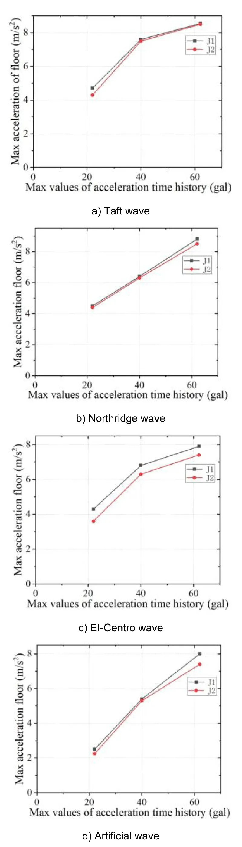
Figure 7: Maximum acceleration of the frame under each seismic waves.
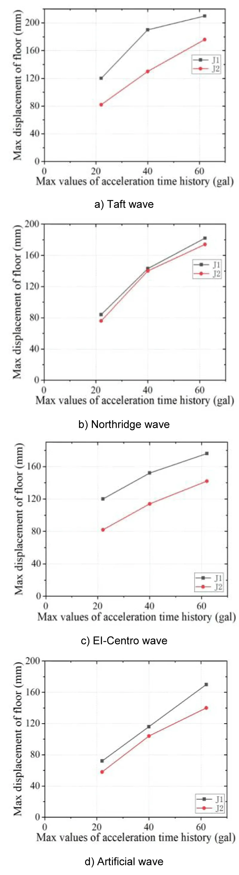
Figure 8: Maximum displacement of the frame under each seismic wave.
The maximum acceleration of the steel frame (J-2 frame) with flange thickened bone node connection is lower than that of the J-1 frame. This is because the rotational stiffness of the flange-widened bone node increases the damping ratio of the overall structure, thereby suppressing the acceleration response. By comparing the acceleration trends of the two frames, it is found that the maximum acceleration of each layer of the two frames is slightly different. Under the action of horizontal seismic waves, the acceleration shows an increasing trend with the increase of the peak value of the seismic wave; this is mainly due to the early yielding of the beam-column node of the steel frame with flange widening skeleton node in the node domain, which makes it enter the plastic stage earlier, thus showing a more significant node response under seismic excitation.
Comparative analysis of the maximum displacement of each layer of the two models
The displacement response analysis of the J-1 and J-2 frames under seismic action is shown in Figure 8. The results in the figure show that under the action of the same seismic wave with different intensities, the maximum displacement of the J-2 frame with a flange widening skeleton node is lower than that of the J-1. This is because the J-2 frame beam-column node is connected by the end flange reinforced skeleton node, which leads to a slight decrease in the overall lateral stiffness of the structure. However, the flexible design of the J-2 frame facilitates the realization of a controllable plastic hinge mechanism and the optimization of the distribution of seismic energy in the spatial dimension.
It can be concluded that when the frame is excited by seismic waves, the overall ductility and energy dissipation capacity of the frame are effectively improved after adding the flange-widened bone node, and the overall seismic performance of the frame is also further improved.
Comparative analysis of the maximum inter-story displacement angle of each layer of the two models
The maximum inter-story displacement angle results of the J-1 and J-2 frames under earthquake action are shown in Figure 9. The results in the figure show:
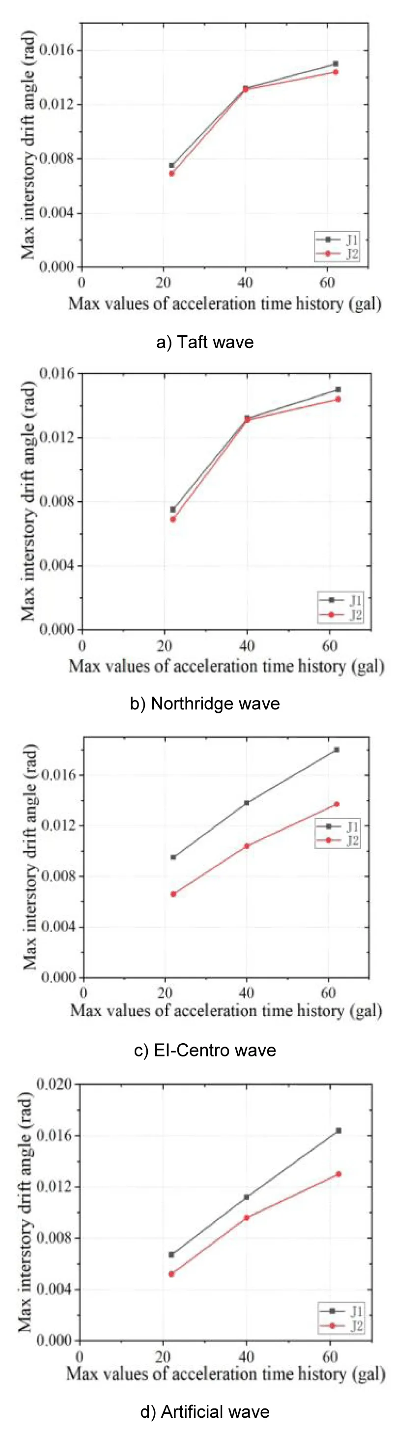
Figure 9: Maximum inter-story displacement angle of the frame under each seismic wave.
Under the rare earthquake condition of 7 degrees, the maximum inter-story displacement angle of the flange widened bone node frame (J-2) is 0.007rad, which is 26.32% lower than that of the steel frame (J-1: 0.095 rad), meeting the elastic-plastic displacement angle limit requirement (0.020 rad) specified in the Code for Seismic Design of Buildings GB50011-2010. When the design intensity is increased to 9 degrees, the displacement angle reduction rate remains at 13.47%, indicating that the new node has a continuous and stable displacement control capability under the action of a large earthquake. Due to the existence of plastic hinges, the horizontal inter-layer displacement angle of each layer of the J-2 frame is lower than that of the J-1 frame. The new node improves the equivalent lateral stiffness and displacement coordination coefficient of the structure through a three-stage collaborative working mechanism: stiffness coordination in the elastic stage, moment redistribution in the elastic-plastic stage, and shear deformation concentration in the plastic stage.
Comparative analysis of the maximum base shear force of each layer of the two models
According to the following Table 5-8, by analyzing the maximum base shear force at the bottom of the column in two directions, it can be obtained that under the action of earthquake waves, the maximum base shear force of the F-2 frame is smaller than that of the F-1 frame, and the maximum base shear force under earthquake action is mainly related to the intensity of the earthquake wave, which is within the reasonable bearing range of the steel structure. Among them, under the action of TAFT waves with a peak acceleration of 4000mm/s², the base shear force of the J-2 frame is reduced by 18.08% compared with the J-1 frame. This is because the addition of the widened flange bone node improves the overall flexibility of the structure and reduces the shear force borne by the column base, which conforms to the node stiffness degradation law. Therefore, it can be concluded that the new node connection can make the structure better absorb and disperse seismic energy during an earthquake, thereby improving the overall stability of the structure.
| Table5: Maximum base shear force of J-1 and J-2 under the taft wave | |||
| Peak earthquake acceleration | 2200 mm/s² | 4000 mm/s² | 6200 mm/s² |
| J-1 Base shear force (kN) | 83.308 | 117.10 | 160.17 |
| J-2 Base shear force (kN) | 82.687 | 114.85 | 156.69 |
| Difference (%) | 0.74 | 1.92 | 2.17 |
| Table 6: Maximum base shear forces of J-1 and J-2 under Northridge wave action. | |||
| Peak earthquake acceleration | 2200 mm/s² | 4000 mm/s² | 6200 mm/s² |
| J-1 Base shear force (kN) | 73.2789 | 124.248 | 138.408 |
| J-2 Base shear force (kN) | 71.9804 | 120.165 | 137.079 |
| Difference (%) | 1.77 | 3.29 | 0.96 |
| Table7: Maximum base shear force of J-1 and J-2 under the action of EI-Centro waves. | |||
| Peak earthquake acceleration | 2200 mm/s² | 4000 mm/s² | 6200 mm/s² |
| J-1 Base shear force (kN) | 107.604 | 133.48 | 163.756 |
| J-2 Base shear force (kN) | 90.7801 | 129.755 | 154.357 |
| Difference (%) | 15.64 | 2.79 | 5.74 |
| Table8: Maximum base shear force of J-1 and J-2 under artificial wave action | |||
| Peak earthquake acceleration | 2200 mm/s² | 4000 mm/s² | 6200 mm/s² |
| J-1 BASE SHEAR FORCE (KN) | 74.8416 | 120.049 | 151.518 |
| J-2 BASE SHEAR FORCE (KN) | 73.1112 | 119.014 | 151.503 |
| Difference (%) | 2.31 | 0.86 | 0.009 |
In this chapter, the simplified modeling method of beam elements is adopted. By establishing a four-layer flange thickened skeleton node frame and a rigid frame refined model, a comparative analysis is carried out, and the influence of flange-widened skeleton nodes on the seismic resistance of steel frames is obtained. The conclusions are as follows:
- The stiffness of the flange-widened bone node is lower than that of the traditional rigid node, resulting in a decrease in the overall stiffness of the frame. This reduces the horizontal displacement of each layer of the structure under earthquake action, optimizes the deformation capacity, enhances the force performance and ductility, and avoids brittle failure caused by excessive stiffness.
- The maximum base shear force of the flange-widened bone node frame is lower than that of the traditional rigid frame, and is within the reasonable bearing range of the steel structure. This node effectively disperses and dissipates seismic energy by increasing the lateral displacement, significantly improving the overall stability of the structure, and reducing local stress concentration and seismic damage.
- The elastic-plastic inter-layer displacement angle of the flange widened bone node frame under rare earthquakes is less than 1/50, which meets the requirements of the "Code for Seismic Design of Buildings" and can achieve the goal of "not collapsing in a major earthquake", reflecting its superior seismic performance.
In summary, the appropriateness of the design of the beam-column node is related to the overall performance of the steel frame, especially the overall performance of the frame under dynamic loads. The seismic analysis results of the steel frame connected by the flange widened bone node meet the requirements of the code under earthquake action. Compared with the traditional rigid node, this node enhances the overall stability, seismic performance, and bearing capacity of the structure.
Funding
This work was supported by the National Natural Science Foundation of China (Grant No. 52279128), Natural Science Foundation of Heilongjiang Province of China (Grant No. YQ2022E013), and High-level scientific research guidance special project (3072022CF0215).
- Li GQ, Mativo J. Approximate estimation of the maximum load of semi-rigid steel frames. J Constr Steel Res. 2000;54(2):213–225. Available from: http://dx.doi.org/10.1016/S0143-974X(99)00044-9
- Wang Y, Li H, Li J. Initial stiffness and structural internal force analysis of semi-rigid beam-column node connection. Eng Mech. 2003;20(6):65–69. Available from: https://engineeringmechanics.cn/en/article/id/3769
- European Committee for Standardization. Eurocode 3: Design of steel structures. Part 1-8: Design of joints. EN 1993-1-8. London: European Committee for Standardization; 2005. Available from: https://www.phd.eng.br/wp-content/uploads/2015/12/en.1993.1.8.2005-1.pdf
- Liu XC, Xu AX, Zhang AL, Ni Z, Wang HX, Wu L, et al. Static and seismic experiment for welded joints in modularized prefabricated steel structure. J Constr Steel Res. 2015;112:183–195. Available from: http://dx.doi.org/10.1016/j.jcsr.2015.05.003
- Liu XC, Pu SH, Zhang AL, Xu AX, Ni Z, Sun Y, Ma L. Static and seismic experiment for bolted-welded joint in modularized prefabricated steel structure. J Constr Steel Res. 2015;115:417–433. Available from: https://daneshyari.com/article/preview/284423.pdf
- Wang H, Zhao X, Ma G. Experimental study on seismic performance of column-column-beam joint in panelised steel-modular structure. J Constr Steel Res. 2022;192:107420. Available from: https://doi.org/10.1016/j.jcsr.2022.107420
- Yan W, Mu T, Xie Z, Cheng Y. Experimental investigation of typical connections for fabricated cold-formed steel structures. Adv Struct Eng. 2019;22(1):141–155. Available from: https://doi.org/10.1177/1369433218781901
- Alamdari MM, Li J, Samali B, Ahmadian H, Naghavi A. Nonlinear joint model updating in assembled structures. J Eng Mech. 2014;140(7):04014042. Available from: https://doi.org/10.1061/(ASCE)EM.1943-7889.0000759
- Zheng LQ, Chen XY, Wei CG, Yan G. Seismic performance of prefabricated beam-to-column joint with replaceable energy-dissipating steel hinge. Bull Earthq Eng. 2022;20(3):1865–1895. Available from: http://dx.doi.org/10.21203/rs.3.rs-725075/v1
- Fan JC, Zhao JH, Hua L, Zhang D, Chen R, Kang Y. Seismic performance and analytical model of CFDST joint with endplates and long bolts. Structures. 2022;35:483–499. Available from: http://dx.doi.org/10.1016/j.istruc.2021.11.034
- Chen LH, Feng JD, Xue Y, Liang C. Seismic behavior of an innovative prefabricated steel-concrete composite beam-column joint. J Build Eng. 2023;76:107211. Available from: https://doi.org/10.1016/j.jobe.2023.107211
- Zhang ZW, Wang HJ, Qian HL, Gao K, An B, Fan F. Design and mechanical performance analysis of a new type of column-column-beam prefabricated steel frame joint. Struct Eng Int. 2021;31(3):418–426. Available from: http://dx.doi.org/10.1080/10168664.2020.1824557
- Zhang YX, Wang ZY, Zhao W, Zhao W, Chen Y. A pseudo-dynamic test study on a self-centering prefabricated steel frame with a column base connected by semi-rigid joints. Adv Steel Constr. 2016;12(3):296–315. Available from: https://www.ascjournal.com/down/vol12no3/Vol12No3_5.pdf
- Li ZH, Qi YH, Teng J. Experimental investigation of prefabricated beam-to-column steel joints for precast concrete structures under cyclic loading. Eng Struct. 2020;209:110217. Available from: http://dx.doi.org/10.1016/j.engstruct.2020.110217
- Du HK, Zhao PF, Wang YD, Sun W. Seismic experimental assessment of beam-through beam-column connections for modular prefabricated steel moment frames. J Constr Steel Res. 2022;192:107208. Available from: http://dx.doi.org/10.1016/j.jcsr.2022.107208
- Yang HB. Performance analysis of semi-rigid connections in prefabricated high-rise steel structures. Structures. 2020;28:837–846. Available from: http://dx.doi.org/10.1016/j.istruc.2020.09.036
- Wu CL, Liu X, Pan W, Mou B. Restoring force model for modular prefabricated steel-reinforced concrete column to H-shaped steel beam composite joints. J Build Eng. 2021;42:102845. Available from: https://doi.org/10.1016/j.jobe.2021.102845
- Wang ZS, Zhu JP, Tian PG, Lu J, Tian J. Hysteretic and rotational performance study of outwardly extending shape-steel prefabricated beam-column joints. J Constr Steel Res. 2023;211:108221. Available from: http://dx.doi.org/10.1016/j.jcsr.2023.108221
- Zhang AL, Wang Q, Jiang ZQ, Yang X, Zhang H. Experimental study of earthquake-resilient prefabricated steel beam-column joints with different connection forms. Eng Struct. 2019;187:299–313. Available from: http://dx.doi.org/10.1016/j.engstruct.2019.02.071
- Zheng LQ, Chen XY, Wei CG, Yan G. Seismic performance of prefabricated beam-to-column joint with replaceable energy-dissipating steel hinge. Bull Earthq Eng. 2022;20(3):1865–1895. Available from: http://dx.doi.org/10.21203/rs.3.rs-725075/v1
- Pan Z, Pan P, Ye L. Finite element simulation and parameter analysis of self-centering steel frame node. J Build Struct. 2011;32(3):35–42.
- Cui F, Wang M, Xia B, et al. Analysis of the influence of semi-rigid connection characteristics on steel frame. Build Struct. 2023;53(s1):1401–1405.
- Shu G, Liu W, Chen S. Theoretical study on direct analysis method of semi-rigid steel frame. J Build Struct. 2014;35(8):142–150. Available from: https://www.researchgate.net/publication/287020292_Theoretical_research_on_direct_analysis_method_for_semi-rigid_steel_frames
- Liu C. Influence coefficient of dog-bone rigid connection steel frame structure [dissertation]. Suzhou: Suzhou University of Science and Technology; 2009.
- Li G, Sun F, Shen Z. Fracture behavior of welded connection of steel frame beam-column under strong earthquake. J Build Struct. 1998;19(4):19–28.
- Ru J, Yang N, Yang Q. A review of performance research on flange-weakened steel frame beam-column joints. Eng Mech. 2004;21(1):61–66.
- Yu Y. Experimental study and theoretical analysis of flange-weakened steel frame beam joints [dissertation]. Xi’an: Xi’an University of Architecture and Technology; 2008.
- Mao H, Wang Y. Research on the mechanical properties of steel frame beam flange expanded wing-shaped nodes. J Xi’an Univ Archit Technol (Nat Sci Ed). 2010;42(1):36–41.
- Zhu S. Research on internal force analysis method of sleeve-jointed prefabricated concrete frame considering semi-rigidity of beam end [dissertation]. Yangzhou: Yangzhou University; 2024.
- Wang X, Han M, Pang K, Chen J, Wang Y. Seismic performance analysis of frame with cantilever beam segment node based on node simplification theory. Ind Constr. 2025 Apr 15 [cited 2025 May 14]. Available from: http://dx.doi.org/10.3724/j.gyjzG24091601
- Wang Z. Research on seismic performance of spring self-reset energy-absorbing beam-column node [dissertation]. Qinhuangdao: Yanshan University; 2022.
- Zhuang Z. Abaqus nonlinear finite element analysis and examples. Beijing: Science Press; 2005.
- Ministry of Housing and Urban-Rural Development of the People's Republic of China. Code for seismic design of buildings: GB 50011-2010 (2016 edition). Beijing: China Architecture & Building Press; 2016.