
More Information
Submitted: March 21, 2023 | Approved: April 25, 2023 | Published: April 26, 2023
How to cite this article: Flisyuk OM, Martsulevich NA, Toptalov VS. Determination of the capture efficiency of a direct-flow cyclone. Ann Civil Environ Eng. 2023; 7: 014-016.
DOI: 10.29328/journal.acee.1001050
Copyright License: © 2023 Flisyuk OM, et al. This is an open access article distributed under the Creative Commons Attribution License, which permits unrestricted use, distribution, and reproduction in any medium, provided the original work is properly cited.

Determination of the capture efficiency of a direct-flow cyclone
Flisyuk OM*, Martsulevich NA and Toptalov VS
St. Petersburg State Institute of Technology, Saint-Petersburg, Russia
*Address for Correspondence: Flisyuk OM, St. Petersburg State Institute of Technology, Saint-Petersburg, Russia, Email: [email protected]
In addition to conventional cyclones, direct-flow cyclones are often used in industry to separate dust and gas systems, despite the fact that in some cases they are inferior to other types of cyclones in their characteristics. This is primarily due to the compactness of these devices and significantly lower metal consumption. These cyclones are generally used for the coarse purification of a large number of gases. The article describes an experimental study of the newly designed direct-flow cyclone capture efficiency. The device has a simple design and low hydraulic resistance. Fine talc with a median particle diameter of 33 μm, a modal diameter of 30 μm and an average diameter of 31 μm was used as a working material. The experiments were carried out using swirlers with different blade swirl angles - 30°, 45° and 60°. The swirlers showed varying degrees of separation. A comparative analysis of the efficiency curves is shown.
Cyclone separators use centrifugal force to separate the discrete phase – solid particles or liquid droplets – from the gas phase. They are widely used for drying and purifying gases due to their simple design, low maintenance costs, safety, stability, and corrosion resistance [1]. A number of these advantages, along with a sufficiently high capture rate, make cyclones a good tool for engineering environmental protection against industrial dust emissions. The material captured from gas streams can be returned to production, which allows the recycling of resources and resource-saving [2].
There are two main types of cyclone separators. The first type, direct-flow cyclones, are cyclones with the axial flow and guide vanes to create rotation. A number of studies of such cyclone separators with the axial flow are known. The second type is cyclones with a tangential gas supply, which are the basis for various designs and new developments [3].
Researchers are actively engaged in developing new and improving existing designs of gas purifiers. Thus, in the work of Jianfei Song and others [4], an experimental and numerical study of a cyclone separator with a tangential gas supply was carried out. The main task of the work was to determine the angle of gas supply to the device, providing the greatest efficiency. The experiments were carried out on talc with a dispersion of 1 μm - 10 μm. To conduct the experiments, the researchers assembled an experimental setup that includes a cyclone, a dispenser, a fan, and a number of auxiliary devices. Aslamova V.S and others [5] developed a direct-flow cyclone for use in the production of mineral wool.
Experiments have shown that the device captures mineral wool fibers well. A particular design feature is the presence of a biconical displacer equipped with fins, while the ribs are plates with axes directed along the gas movement trajectory. Lingzhi Wang and others [6] describe a cyclone with a multilayer central channel. A special feature of the cyclone is the multi-stage and multiple twisting of the incoming gas flow. The design made it possible to increase the most effective speed of the incoming polluted gas flow into the device and at the same time to increase maximum efficiency.
Our research group has developed and patented the design of a direct-flow cyclone (Figure 1) [7]. The device consists of coaxially arranged pipes for the gas inlet and outlet. A blade swirled with profiled blades is installed in the inlet pipe. The blade profile provides shock-free entry and exit of the gas flow from the swirl, which reduces its turbulence. After the straight section with the swirler, there is a section with an extension in the form of a truncated cone. The entrance diameter of this section is 150 (d) cm, and the truncated cone is 185 (1.25d) cm long and has a taper of 12. After passing through the inlet pipe, the gas passes to the exhaust pipe to exit the gas. The first part of the gas outlet pipe is a truncated cone with base diameters of 120 (0.8d) cm and 150 (d) cm. The device has a low-pressure drop – 400-600 Pa – and a simple design.
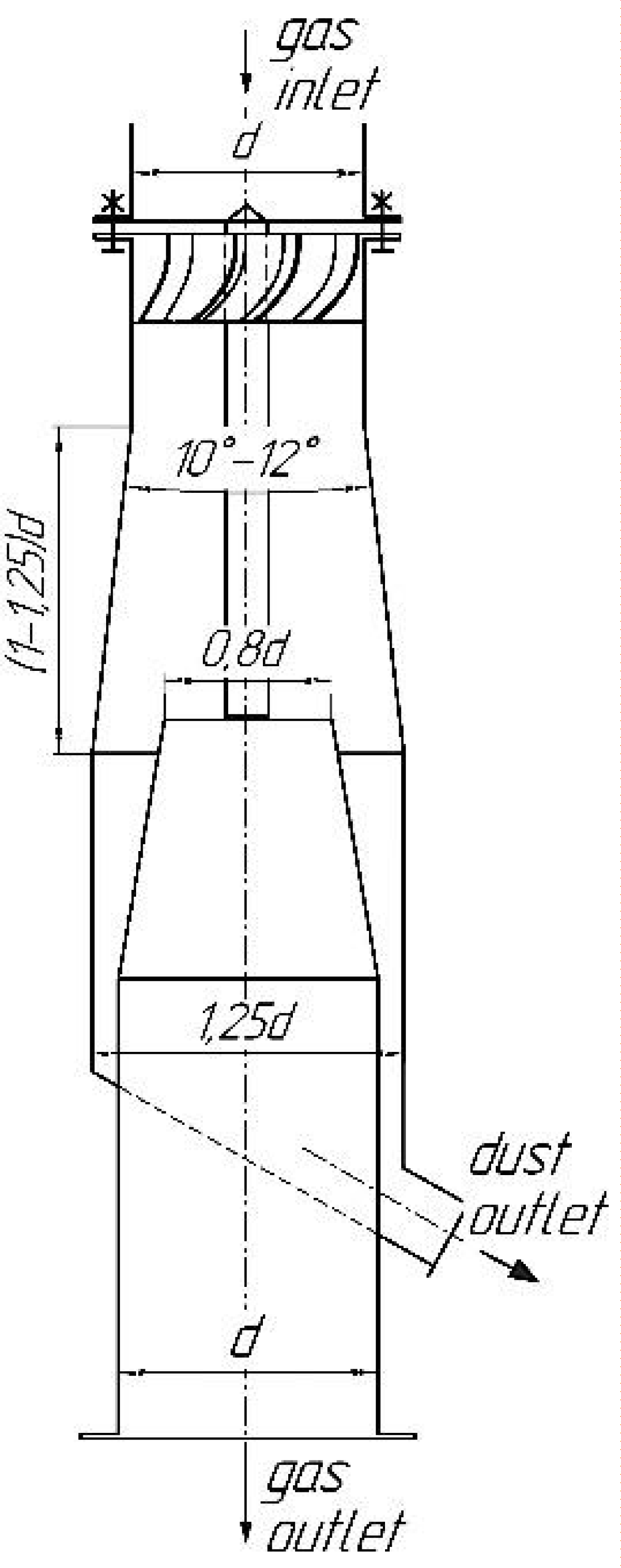
Figure 1: Scheme of the investigated direct-flow cyclone.
The cyclone developed has several advantages over other similar devices. The patent [8] describes an in-line cyclone separator that includes a large swirler consisting of three parts: two cylindrical parts with blades and vanes, and a conical part with screw-like notches. In the patent [9] the authors describe a separator for separating a solid, liquid, and gas mixture. The apparatus also includes a complex multi-component swirler, the main structural part of which is a torpedo-shaped stabilizer with a steeply twisted spiral. Such structural parts and components complicate the designing and calculation of devices, and their production requires significant material costs. The axial flow-type cyclone described in the patent [10] has a design similar to the device we developed. But its disadvantage is the lack of a smooth transition in the branch pipe for the outlet of the purified gas stream. This increases the turbulence of the flow and the pressure drop in the device.
We have conducted a study of its effectiveness on a number of finely dispersed materials, including those with a polydisperse composition - ground talc. To carry out the experiments, an experimental setup was assembled; the layout of the setup is shown in Figure 2.
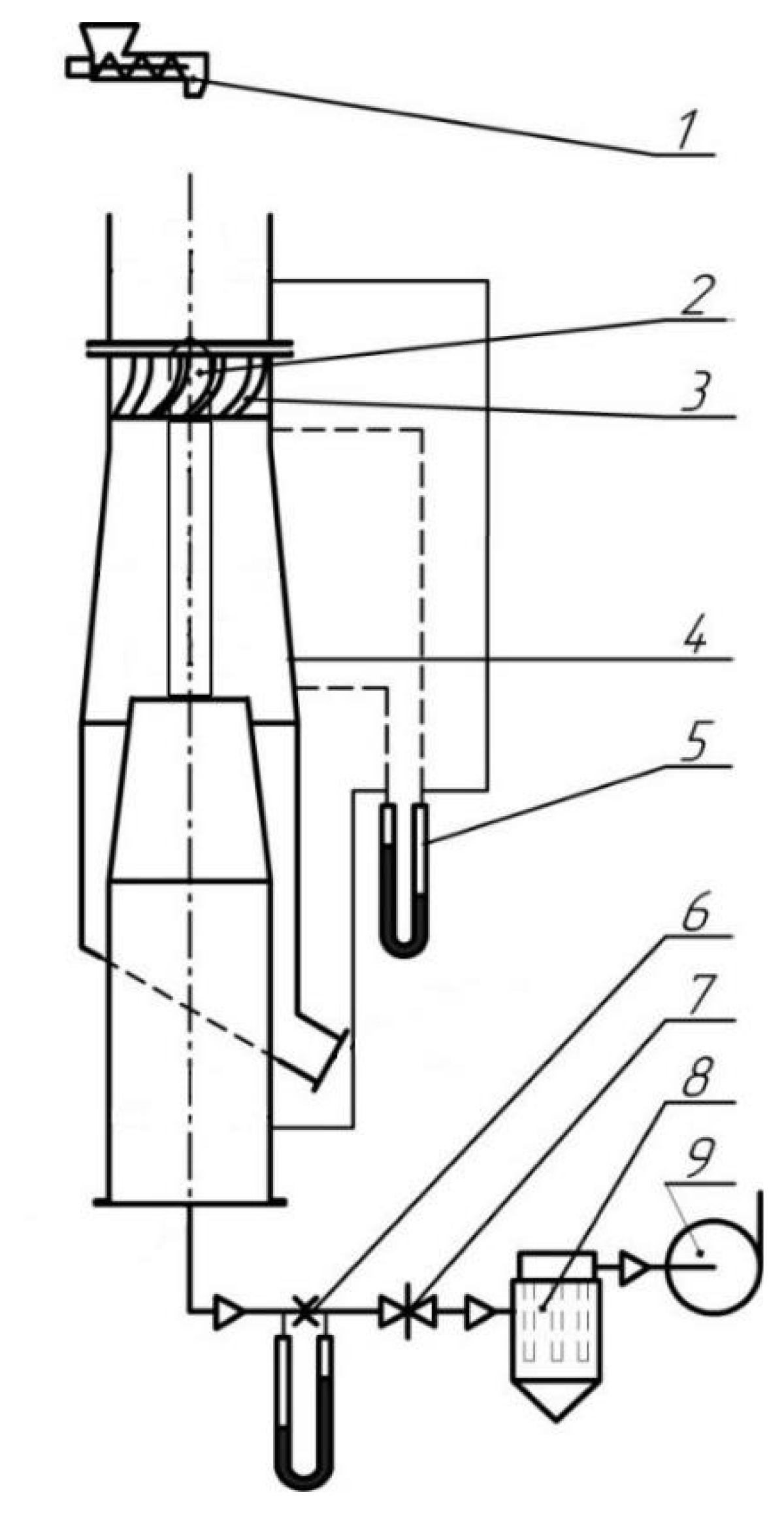
Figure 2: Scheme of the experimental setup. 1: Screw dispenser; 2: Swirler; 3: Swirler blade; 4: Case of a direct-flow cyclone; 5: Differential pressure gauge; 6: Diaphragm with a differential pressure; 7: Slide gate; 8: Bag filter; 9: Centrifugal fan.
The initial material was analyzed for the dispersed composition, which was determined by laser diffraction (LD) on the particle analyzer SALD-2300 (Shimadzu, Japan). Before analysis, a sample of powder weighing 100-120 mg was dispersed in distilled water while stirring on a magnetic stirrer for 3 minutes. The refraction coefficient of the sample was 1.65-1.7. To check the particle size scale we used: the standard sample (SS) from the device kit, SS of monodisperse polystyrene latex, and SS of powdered material.
The results of the analysis showed that talc has a median particle diameter of 33 µm, modal of 30 µm and an average of 31 µm. In addition, from the analysis, it can be concluded that 80% of the particles in the sample are less than 76 µm. The particles are distributed in the range from 1 µm to 200 µm, but their bulk falls in the range between 10 µm and 150 µm. This particle size is the target for investigating the effectiveness of the developed direct-flow cyclone. The source material sample analysis results are shown in Figure 3.
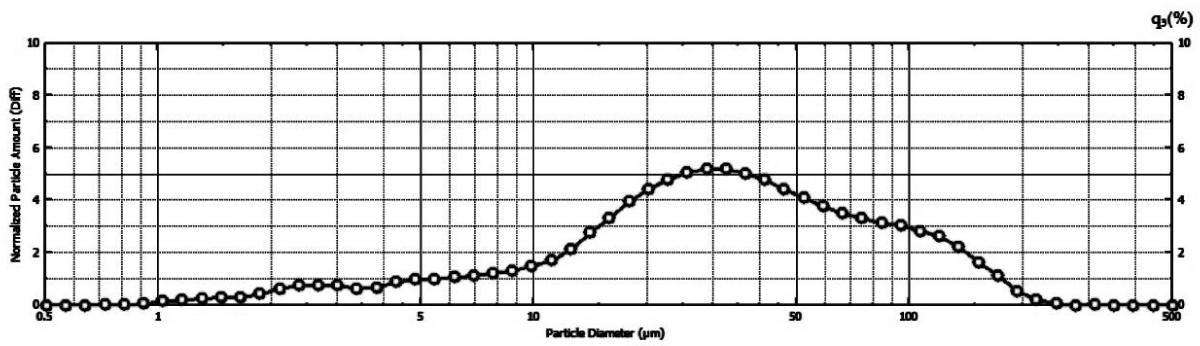
Figure 3: Dispersed composition of the initial material (talc).
The capture efficiency dependence of the above-described talc by a cyclone using swirlers with three different blade swirl angles on the gas flow rate is shown in Figure 4. The flow rate of 13 m/s was the most effective. The largest percentage of captured particles – 95% – was expectedly shown by a swirler with a 60° blade twist angle. The device with a swirler with 45° blade twist angles showed an efficiency of 91%. Such twist angles provided sufficient rotation of the flow to create the centrifugal force necessary to throw particles to the walls. A small twist angle of the swirler blades – 30° – was not enough to create a strong swirl and the flow carried the particles into the outlet branch pipe. The efficiency of the cyclone separator with such a swirler turned out to be significantly lower than with the previous two. The highest percentage of particles captured - 95% - was expectedly shown by a swirler with a blade swirl angle of 60°.
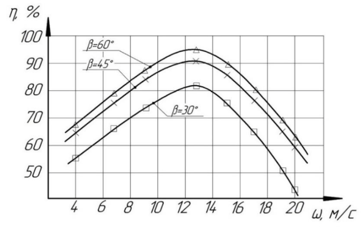
Figure 4: Talc capture efficiency.
The paper shows that a cyclone separator of a simple design can show high efficiency even when capturing fine materials. Correctly chosen constructive ratios have a key influence on the degree of separation.
An important part of the device is the swirler. Its design, the blade swirl angle, and its profile can greatly affect the number of particles captured.
The results of the conducted studies have shown that a cyclone of this design provides a sufficiently high separation efficiency even for fine materials.
The study was supported by a grant from the Russian Science Foundation (project 21-79-30029).
- Cristobal C, Gil A. Modeling the gas and particle flow inside cyclone separators. Progress in Energy and Combustion. 2007; 33(5):409-452. https://doi.org/10.1016/j.pecs.2007.02.001
- Peng W, Hoffmann AC, Dries HWA, Regelink MA, Stein LE. Experimental study of the vortex-end in centrifugal separators: the nature of the vortex end. Chem Eng Sci. 2005. 60: 6919–6928. https://doi.org/10.1016/j.ces.2005.06.009
- Malikov ZM, Madaliev ME. Mathematical modeling of turbulent flow in a centrifugal separator // Bulletin of the Tomsk State University. 2021. 71:121-138. https://doi.org/10.17223/19988621/71/10
- Song J, Wei Y, Sun G, Chen J. Experimental and CFD study of particle deposition on the outer surface of vortex finder of a cyclone separator. Chemical Engineering Journal. 2017; 309:249-262. https://doi.org/10.1016/j.cej.2016.10.019
- Aslamova VS, Aslamov AA, Lyapustin PK, Museva TN, Bragin NA. Direct-flow cyclone for the production of industrial wool. Ecology and industry of Russia. 2007; 6: 26-27.
- Wang L, Liu B, Feng J, Peng X. Experimental study on the separation performance of a novel oil–gas cyclone separator. Powder Technology. 2023; 415:118124. https://doi.org/10.1016/j.powtec.2022.118124
- Patent RU195672U1. Flisiyk OM, Toptalov VS, Martculevich NA, Muratov OV. Direct-flow cyclone. 2020. B04C 3/00, B04C 3/06.
- Patent US20080006011A1. Per-Reidar Larnholm, Robert Schook. In-line cyclone separator. 2008. BO1D 45/14.
- Patent EP1919590B1. Robert Schook, GJ Steenderen. Separator for separating a solid, liquid and/or gas mixture. 2008. B01D 19/00, B04C 3/06, B01D 17/02.
- Patent WO2013147373A1. Axial flow-type cyclone dust collection device. 2013. B01D 45/12, B04C 5/103.