
More Information
Submitted: July 16, 2022 | Approved: August 01, 2022 | Published: August 02, 2022
How to cite this article: Rashiddel A, Dias D. Efficiency of different methods for calculating the mechanized tunnels face pressure considering an earth pressure balance. Ann Civil Environ Eng. 2022; 6: 040-041.
DOI: 10.29328/journal.acee.1001038
Copyright License: © 2022 Rashiddel A, et al. This is an open access article distributed under the Creative Commons Attribution License, which permits unrestricted use, distribution, and reproduction in any medium, provided the original work is properly cited.
Keywords: Ground stiffness; Mechanized excavation; Face pressure; COB method; Limit equilibrium method; Numerical modeling

Efficiency of different methods for calculating the mechanized tunnels face pressure considering an earth pressure balance
Alireza Rashiddel1 and Daniel Dias2*
1Department of Civil Engineering, ISISE, University of Minho, Campus de Azurém, 4800-058 Guimarães, Portugal
2Department of Geotechnical Engineering, Grenoble Alpes University, Laboratory 3SR, Polytech Grenoble, France
*Address for Correspondence: Daniel Dias, Department of Geotechnical Engineering, Grenoble Alpes University, Laboratory 3SR, Polytech Grenoble, France, Email : [email protected]
Different methods for calculating and estimating a safe face pressure were proposed by researchers, which have some advantages and disadvantages. In each of these methods, some related parameters such as soil geotechnical parameters, dimensions of the tunnel, and geological conditions are used. In these methods, using a series of mathematical or empirical functions, the face pressure is calculated. In this study, the face displacements were obtained using the finite difference numerical FLAC3D, the COB (Netherlands Underground Science Center) empirical, and the Leca and Dormieux (1990) analytical methods. The impact of the COB method on different ground stiffnesses is studied and evaluated. The reference case of this research is the Tehran Metro Line 6 tunnel (excavation radius: 4.6 m).
In tunneling when dealing with Earth Pressure Balance (EPB) tunnel boring machines (TBM), three zones around the tunneling machine can create ground movements. The first one is at the tunnel face due to the difference between the applied TBM pressure and the soil one. The second one is located around the TBM shield due to the shield conicity (the cutter head’s outer diameter is larger than the shield end). In the last zone, the movements at the shield end are due to the tail void gap (difference between the shield outer diameter and the tunnel lining [1-4]). Meanwhile, the surface settlement contribution due to the face displacements is commonly in the range of 25% to 30% [1] and applying optimal face pressure prevents excessive deformations of these areas. TBMs have great abilities for excavations in unstable grounds like sandy ones under the groundwater table. By increasing the urban tunnel size, a precise estimate of the amount of variation of the tunnel face pressure on the different grounds to reduce the risk of damage to ground-level buildings is necessary. This essential and critical parameter is essential for preventing the tunnel face instabilities and ground settlements. The face pressure will directly impact the machine’s performance and the number of settlements or uplifts of the tunnel excavation path.
Figure 1 shows the horizontal deformation values of the tunnel face by the two methods of the COB and Leca & Dormieux. As can be seen, the face pressure obtained from the COB method shows smaller horizontal deformations than the Leca & Dormieux one. The case without face pressure is also presented. In both methods, the maximum horizontal deformations value is smaller than 1% of the excavation radius. The results show that the number of face deformations produced by the analytical and empirical methods differ. Also, according to Figure 2, with the decrease of Young’s Modulus of the ground, the face’s horizontal deformation increases and exceeds the permissible value of 1% of the excavation radius. Using analytical and empirical methods considering a ground Young’s Modulus smaller than 50 MPa is incorrect as the horizontal movements are in this case greater than in the case without face pressure.
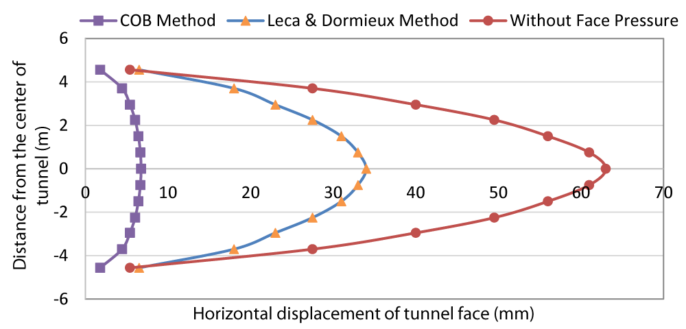
Figure 1: Horizontal displacement of tunnel face with the COB method, the Leca and Dormieux one and the 3D numerical modelling.
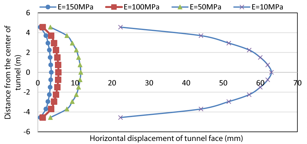
Figure 2: Horizontal displacements of the tunnel face with the COB method considering different ground Young’s Modulus (obtained with the 3D numerical modelling).
- Thewes M, Budach C. Grouting of the annular gap in shield tunneling – an important factor for minimization of settlements and production performance. In: Proceedings of the ITA-AITES World Tunnel Congress, Safe Tunneling for the City and Environment, Budapest, Hungary, 23 to 28 May, 2009.
- Guglielmetti V, Grasso P, Mahtab A, Xu S. Mechanized Tunnelling in Urban Areas. Taylor & Francis Group, London, UK. 2008.
- Leca E, Dormieux L. Upper and Lower Bound Solutions for The Face Stability of Shallow Circular Tunnels in Frictional Material. Geotechnique. 1990. 40: 581-606.
- GMBH Consulting Engineers. Report on the static design of the segmental lining for MetroTehran Line 6. Tehran Urben Railway Corporation. 2011.