
More Information
Submitted: 13 April 2020 | Approved: 08 May 2020 | Published: 11 May 2020
How to cite this article: Aliyev IH. Studies of the possibility of determining amplifications in kinematic pairs. Ann Civil Environ Eng. 2020; 4: 012-014.
DOI: 10.29328/journal.acee.1001020
Copyright License: © 2020 Aliyev IH. This is an open access article distributed under the Creative Commons Attribution License, which permits unrestricted use, distribution, and reproduction in any medium, provided the original work is properly cited.
Keywords: Kinematic pairs; Acceleration; Vector; Inertia; Tangential acceleration; Gravity; Angular acceleration

Studies of the possibility of determining amplifications in kinematic pairs
IH Aliyev*
Doctor, Philosophy in Technology, Azerbaijan State Agrarian University, Ganja, Azerbaijan
*Address for Correspondence: IH Aliyev, Doctor, Philosophy in Technology, Azerbaijan State Agrarian University, Ganja, Azerbaijan, Tel: +994504242130; Email: [email protected]
The article discusses approaches to solving problems of accurately determining strength in kinematic pairs. It is known that the nature of the bonds imposed by kinematic pairs is determined by the geometric shapes of the elements of the pairs. For what, here, the bonds acted during the entire time the mechanism was moving, so that the elements of the kinematic pairs would continuously touch each other. Where it is recognized that one of the simplest methods for taking into account the inertia of a link is the principal moment method. How the contradiction is sought is here because the normal acceleration has a direction opposite because normal acceleration has a direction opposite to the link (directed toward the center), and the image of tangential acceleration is directed parallel to this acceleration. The following simplification can be made if the main vector of inertia is considered together with the weight of the link.
The solids from which the mechanism is formed are called links. This refers to both absolutely rigid, and deformable and flexible bodies. Liquids and gases in the theory of mechanisms are not considered links. A link is either one part or a combination of several parts.
Study materials
United in one kinematic immutable system. The links are distinguished by design features (piston, gear, connecting rod, etc.) and but by the nature of their movement.
For example, a link that rotates a full revolution around a fixed axis is called a crank; for an incomplete revolution, a field is covered: a ring about a slider that performs linear translational motion, etc. kinematic links: a pair is called the lowest, whether its elements of the links touch only along the surface and the higher, if only along the lines or at the points.
The nature of the bonds imposed by kinematic pairs is determined by the geometric shapes of the elements of the pairs. In order for the bonds to act throughout the entire movement of the mechanism, the elements of the kinematic pairs must continuously touch each other.
Study moves
One of the simplest methods for accounting for link inertia is the principal moment method. The disadvantage of this method is partial errors for certain directions of angular acceleration.
To avoid this, we can suggest the following rule: on the acceleration plate, the angular acceleration of the link is directed from full acceleration to normal.
How a contradiction is sought is because the normal acceleration has a direction opposite because the normal acceleration has a direction opposite to the link (directed toward the center), and the image of the tangential acceleration is directed parallel to this acceleration (Figure 1).
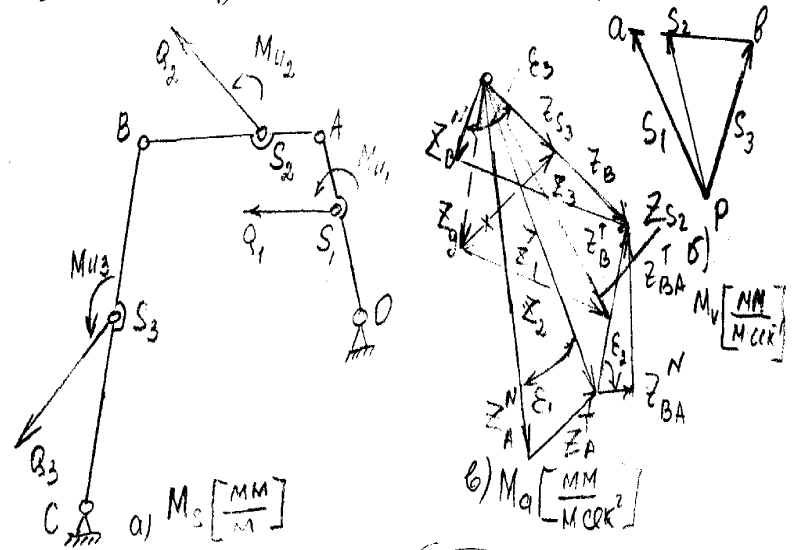
Figure 1: Depicting the centers of gravity of the links.
The following simplification can be made if the main vector of inertia is considered together with the weight of the link.
We will call them the combined force and denote by с with the link index, and denote the image of the corresponding acceleration by Z with the same index.
To do this, on the acceleration plan, it is necessary to subtract the acceleration of gravity from the acceleration of the center of gravity of the link.
The opposite sign for the acceleration of gravity was obtained because this acceleration is parallel to the weight, while the inertia is directed opposite to the corresponding acceleration.
Graphically, this reduces to the fact that it is necessary to take the new pole down in terms of accelerations at a distance equal to the image of the acceleration of gravity Zg = M_ag, where Ma [mm/(m s 〖s〗 ^ (- 2)] The scale of the acceleration plan. the pole must connect all the points of the plan of accelerations depicting the centers of gravity of the links.
Based on the obtained segments (they are shown by a dotted line in figure), we can determine the magnitude and direction of the combined forces of each link.
A third simplification can be obtained if, in the formulas for determining the moments (which are substituted into the equilibrium equation), constant values are calculated once for all positions of the mechanism. For external forces and forces in kinematic pairs, this formula will take the form:
M_Q ^ A = (W_Q h_Q ^ OA)/(M_Q M_S) (1)
where M_Q ^ A is the moment of force Q relative to point A;
W_Q - a segment depicting the strength of Q;
M_Q - force scale mm/kg
M_S - length scale mm/kg
H Q ^ A - image of the nega force Q in the drawing, mm.
The value of the product MqMs (mm2/kg.m) is calculated once for all positions of the mechanism.0
The moment of the combined force Qi (as well as the moment of inertia) is determined through the mass mi– acceleration Z i / Ma - and another force h_Qi/M_s;
〖M〗 _Qi ^ A = m_i z_i/M_a ∙ (h_Qi)/M_S = (z_i h_Qi ^ A)/(M_Q ∙ M_S) (2)
The value MiMs/m_i [mm ^ 2/(kg.m)] is also calculated once for all positions (this value is taken in the banner of the body for the convenience of calculations on a slide rule).
The formula for the inertial moment will be
M_Ui = L_i ε_i = L_i Z_T/M_a ∙ 1/L_1 = Z_T/((M_a L_i)/L_i) (3)
where Z_T is the image of the tangential acceleration of one end of the link relative to the other;
The value (MaL_i)/L_i [mm/(kg.m)] is also calculated once for all positions.
To control the correctness of the calculations of the constant values in formulas (1), (2) and (3), a comparison of them for different parts of the mechanism can serve;
The constant values M_a M_e in the formula (1) are the same for all links; the constant values (M_a M_s)/m_i in the formula (2) for various links are inversely proportional to the masses.
The constant values (Ma Li)/Li in the formula (3) for various links are directly proportional to their length and inversely proportional to the moment of inertia.
It should be noted that the derived formulas are suitable not only for taking into account inertia by the main vector and main moment method, but also for other methods, for example, still mass.
Editing in the latter case, formula (3) becomes unnecessary.
- Artolevsky NI. Theory of mechanisms and machines. IN Artobolevsky-M; Alliance, 2008; 640s.
- Artobolevsky II. Theory of mechanisms and machines: Textbook for technical colleges, 4th ed., Rev. and add. - M.: Science. Ch. ed. Phys Math lit. 1988; 640.
- Arutyunov SS. On the structure and classification of kinematic pairs and chains replacing them. Tr. Cargo, Polytechnic Institute, Institute. 1961; 9: 95-111.
- Dvornikov LT, Zhivago E Ya. Two-contact two-moving kinematic pair. RF patent No. 2137964 dated 09/20/1999
- Dvornikov LT, Zhivago E Ya. Self-aligning five-pin rotational kinematic pair. RF patent No. 2137965 from 09/20/1999
- Janitors JI, Zhivago T, E Ya. Two-pin kinematic pair. RF patent No. 2098701 dated 03/06/96 Bull. No. 34. 1997
- Janitors JI, Zhivago T, E Ya. Fundamentals of the theory of kinematic pairs. Monograph. SibGIU Novokuznetsk, 1999; 102.
- Zhivago E Ya. The synthesis technique of kinematic pairs for given complexes of relative movements of the links. Novokuznetsk: SibGIU, 2000; 28.
- Zhivago E Ya. Fundamentals of the theory of kinematic pairs of mechanical systems. Collection of reports of the Republican scientific and technical conference "Modern problems of the theory of mechanisms, machines and engineering." Toshkent, 1999; 12:17.
- NB Yablonsky AA. The course of theoretical mechanics. Textbook for tech. universities. 7th ed. stereotypical. St. Petersburg: Publishing House "Lan". 1998; 768.
- Ross A. The Kinematics of a Space suit Shoulder Joint. Proceedings of Tenth World Congress on the Theory of Machines & Mechanisms. 1999; 2: 467-462.
- Ozgoren MK. Kinematic Analysis of spatial Mechanisms using exponential rotation Matrices. . Proceedings of Tenth World Congress on the Theory of Machines & Mechanisms. 1999; 2: 467-462.
- 0zol OG. Fundamentals of the design and calculation of mechanisms. Riga. Zvaigzne. 1979; 360.