Research Article
Hydraulic jump experiment in a rectangular open channel flume

Mostafa M El-Seddik*
Sanitary and Environmental Engineering, Civil Engineering Department, Faculty of Engineering, Cairo University, Cairo, Egypt
Institute of Aviation Engineering and Technology (IAET), Giza, Egypt
*Address for Correspondence: Dr. Mostafa M. El-Seddik, Sanitary and Environmental Engineering, Civil Engineering Department, Faculty of Engineering, Cairo University, Tel: +201097931177, +201223623360; Email: [email protected]
Dates: Submitted: 05 June 2017; Approved: 27 June 2017; Published: 29 June 2017
How to cite this article: El-Seddik MM. Hydraulic jump experiment in a rectangular open channel flume. Ann Civil Environ Eng. 2017; 1: 042-048. DOI: 10.29328/journal.acee.1001005
Copyright License: © 2017 El-Seddik MM. This is an open access article distributed under the Creative Commons Attribution License, which permits unrestricted use, distribution, and reproduction in any medium, provided the original work is properly cited.
Keywords: Critical depth; Froude number; Hydraulic jump; Supercritical flow; Shear force

ABSTRACT
This paper presents a laboratory experiment for the formation of hydraulic jump in a rectangular open channel flume to accurately explore the effect of flow structures on water resources. This experiment illustrates the behavior of super-critical flow under sluice gate for various flow rates and downstream depths. Several runs are carried out using Armfield Model No. C4-MKII-5.0-11 to investigate the former computations concerning both the downstream conjugate depth and the critical depth resulting within the jump. Moreover, the model is examined to explore the sensitivity of Froude number by adjusting the flow-meter and over-shot weir in the flume. Also, the type of jump attributed to flow velocity can thus be obtained. Furthermore, both location of hydraulic jump and energy dissipated are discussed under the influence of different gate openings.
INTRODUCTION
Hydraulic jump in open channels can be attributed to rapidly varied flow where a significant change in velocity occurs from super-critical flow to sub-critical flow. This fact may owe to the presence of some structures obstructing the movement of flow in open channels. Under-shot weir or gate is the most impressive example for hydraulic jump formation in canals where the flow undergoes high velocity under gates with upstream small depth and returns back to a higher downstream conjugate depth away from the gate with lower velocity. Froude number represents the clear impact of non-uniform flow velocity in open channels where super-critical flow is obtained at Froude number greater than 1, whereas sub-critical flow is indicated at Froude number less than 1. The main advantage of hydraulic jump occurrence in canals is energy dissipation downstream spillways where accumulation of water behind the gate is associated to the high flow velocity which abruptly declines downstream gate and thus avoiding bed erosion and scour. In 1818, experiments were firstly performed by Bidone for hydraulic jump examination. Several models were later proposed to illustrate the characteristics of super-critical flow in open channels [1-5]. Consecutively, researches have managed to introduce analytical and empirical computations for the length of hydraulic jump, energy loss and influence of different gate openings on hydraulic jump formation [6-8]. Further studies have been discussed to show the relationship between conjugate depth ratio, Froude number and energy dissipated in the hydraulic jump [9]. Mathematical models based on experimental studies have currently revealed an attractive way to demonstrate the influence of various parameters on canal performance. Moreover, such models provide a beneficially robust tool to ensure the obtained outcomes and approach more accurate results. However, the former computations ignore the existence of shear force in hydraulic jump formation. In this regard, former equations concerning hydraulic jump included in table 1 are utilized to simulate the flow behavior and compared with the measured outcomes of an experimental flume (Armfield Model No. C4-MKII-5.0-11). Also, the influence of flow structures on water level variation is studied to reveal shear force existence due to bed roughness [10-12]. In this paper, several laboratory experiments are accomplished to explore the upstream conjugate depth for various discharges and downstream water depths by adjusting both flow meter and over-shot weir. Also, the type of hydraulic jump can be observed by simulating Froude number responsible for super-critical flow under the impact of upstream conjugate depth. A novel alternation is developed to express the response of hydraulic jump accompanied by critical depth exploration using various flow structures. Furthermore, the location of jump coupled with energy dissipated is investigated by varying the sluice gate openings in the flume..
MATERIALS AND METHODS
Experimental open channel flume
Laboratory experiments are carried out on a rectangular open channel flume 5 m long (Armfield Model No. C4-MKII-5.0-11) and a basic hydraulic bench (Armfield Model No. F1-10-A) as shown in figure1. The open channel width is 10 cm, whereas the maximum water depth can reach about 30 cm. The transparent side walls of channel are made of acrylic glass, whereas the bottom is made of stainless steel. The flume is provided with a digital flow meter for discharge measurement. Also, a point gauge is implemented for measuring water depth. An over-shot weir is installed at the end of the channel to control water depth while a sluice gate is installed in the open channel to form the hydraulic jump. The basic hydraulic bench includes a submersible pump that supplies the flume with the required discharge controlled by a valve. The water flows through a connected pipe beneath the flume where flow returns back to the hydraulic bench in a closed cycle flow. Several experimental runs are performed by varying the discharge and measuring the corresponding conjugate depths. Accordingly, Froude number can be indicated for both sub-critical and super-critical flows. Also, the length of jump can be measured by a calibrated scale on the top of channel. Moreover, the location of hydraulic jump can be determined by varying the gate openings. The former analytical models are simulated and compared with the experimental results in order to overcome the improper defects in such models and develop a new mathematical model that maintains more accurate outcomes. Table 1 shows the former equations regarding the relation between conjugate depths and flow discharge, energy dissipated in the hydraulic jump and the influence of upstream conjugate depth on Froude number for different velocities.
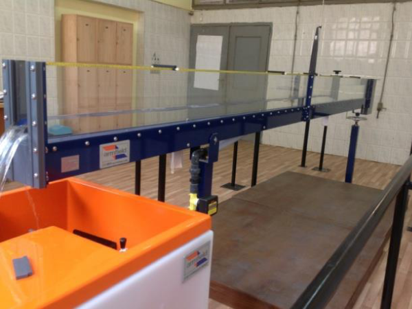
Figure 1: Open channel Armfield flume Model No. C4-MKII-5.0-11 with a basic hydraulic bench Model No. F1-10-A.
| Table 1: Former equations for hydraulic jump occurrence in rectangular open channel flumes. | |
| Description | Equation |
| Downstream conjugate depth | |
| Froude number of super-critical flow | |
| Critical depth | |
| Energy dissipated in jump | |
| Momentum and energy principles | |
RESULTS AND DISCUSSION
Super-critical flow and Froude number simulation
Froude number is associated with the change of water depth and discharge in open channels. Figure 2 shows the simulation results of downstream conjugate depth (Y2) by varying upstream conjugate depth (Y1) and flowing discharge (Q) in the conjugate depth equation mentioned in table 1. Figure 2a, illustrates that the upstream conjugate depth decreases as the downstream conjugate depth increases at constant discharge, whereas an increment in the downstream depth is obtained as discharge increases at constant upstream depth. Figure 2a also indicates that Y2 reaches about 0.1m at Y1 of 0.01m and specific discharge (q) of 0.01m3/sec/m. Accordingly, figure 2b indicates that the Froude number at the upstream depth boosts as upstream depth declines that can be attributed to the increase in flow velocity. On the other hand, an enhancement in the upstream Froude number is achieved by increasing the flow discharge at constant upstream depth as shown in figure 2b. Moreover, a significant increase in Froude number is recognized as a result of a minor decrement in the upstream depth compared to the change in flow discharge that can lead to bed scouring.
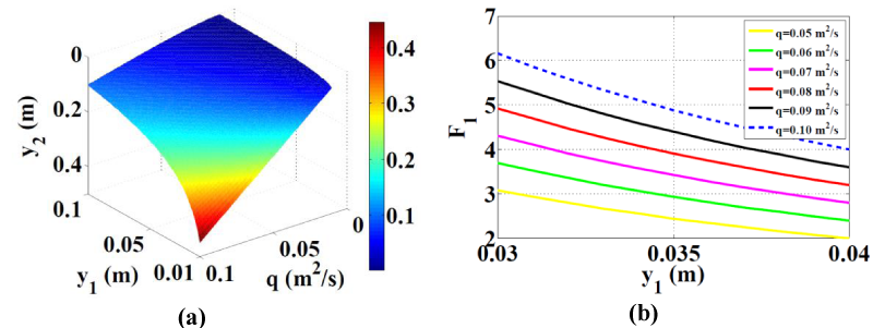
Figure 2: Upstream conjugate depth versus (a) downstream conjugate depth for various discharges per unit width of flume and (b) Froude number at different super-critical flows.
Experimental results
Specific force at gate vena-contraction
Several experimental runs were carried out in the laboratory to reveal the impact of the sluice gate on the location and type of hydraulic jump (Table 2). The experimental results demonstrate that the hydraulic jump approaches the sluice gate as the gate opening increases till the gate becomes submerged. The reason behind this fact may owe to the decline in the velocity under gate as it is raised and accordingly the specific force at the jump overcomes that of the gate vena-contraction. However, the formation of eddy currents in the hydraulic jump is relevant to the constant reverse slope [13]. Also, the obtained results indicate that the type of the hydraulic jump is associated with both the installed gates and the discharge. Regarding supercritical flow, Froude number (F1) increases from 1.1 to 1.5 at run 1,2 respectively as Q increases from 20 to 30 l/min for constant Y2 and gate opening (d). On the other hand, F1 can be boosted from 1.4 to 2.6 by increasing Y2 from 5cm to 6cm for constant discharge and gate opening as shown in run 7,8, respectively. Compared with the measured results, the simulated Y2 reveals a higher value of about 10 cm at Y1 of 0.01 m and Q of 50 l/min. Thus, former computations should be enhanced with shear force existence to obtain more accurate results. However, the minor change between simulated and measured results may owe to the small dimensions of flume and low discharge. It is also evident from results that both the location of hydraulic jump and water depth behind the gate (H) are attributed to the gate opening coupled with discharge at constant conjugate depths. However, Y2 may affect hydraulic jump position as shown in run 5,6,7,8, included in Table 2. Moreover, the length of jump increases and Y1 decreases by increasing Y2 as indicated in run 5,6,7,8, included in Table 2. Furthermore, the change in upstream and downstream depth leads to a change in the energy of an average 0.06 m[14,7].
| Table 2: Experimental runs for the location and type of hydraulic jump at various gate openings (d) and discharges (Q). | |||||||
| Run | d (m) | Q (l/min) | Y1 (m) | Y2 (m) | H (m) | F1 | F2 |
| 1 | 0.005 @ 4.19m |
20 | 0.01 @ 4.05m |
0.03 @ 4.00m |
0.14 | 1.1 | 0.2 |
| 2 | 30 | 0.01 @ 3.70m |
0.03 @ 3.65m |
0.19 | 1.5 | 0.3 | |
| 3 | 0.007 @ 4.19m |
40 | ND* | 0.03 | 0.09 | submerged gate | |
| 4 | 30 | 0.01 @ 3.65m |
0.03 @ 3.70m |
0.17 | 1.5 | 0.3 | |
| 5 | 0.01 @ 3.00m |
30 | ND* | 0.03 | 0.12 | submerged gate | |
| 6 | 40 | 0.013 @ 2.50m |
0.45 @ 2.37m |
0.22 | 1.4 | 0.2 | |
| 7 | 50 | 0.015 @ 2.35m |
0.05 @ 2.25m |
0.21 | 1.4 | 0.2 | |
| 8 | 0.01 @ 3.00m |
0.06 @ 2.75m |
0.21 | 2.6 | 0.2 | ||
Validation of the hydraulic jump model
The experimental work was accomplished in the laboratory to explore the critical depth and the conjugate depths of hydraulic jump as shown in figures 3,4. Two slots 2.5 cm and 1 cm are installed as overshot weir at the end of the flume to control Y2. Figure 3a,c shows that the measured Y1 and Y2 reach 2 cm and 6 cm, respectively at 2 cm gate opening and measured flow rate of about 67.3 l/min as shown in figure 3b. However, the critical depth can theoretically be indicated as 2.3 cm. Accordingly, the jump occurs just downstream sluice gate with Y1 of about 2.3 cm in such case. On the other hand, a broad crested weir is used instead of the gate to determine the characteristics of hydraulic jump as shown in figure 3d. Consecutively, another experimental run is performed to verify the critical depth as illustrated in Figure 4. The gate opening is reduced to 1.5 cm and the flow rate is adjusted at 53.5 l/min as indicated in figure 4a,b, respectively. The depth of water behind gate increases to 22 cm as the gate is lowered step by step in order to form the jump just after gate. The measured critical depth can be assessed as 2 cm that agrees with the theoretical calculation, whereas Y1 and Y2 approach 1.5 cm and 5.5 cm, respectively. Also, same results can be obtained for the hydraulic jump using a crump weir where the difference in upstream levels of jump is about 1.5 cm at Q of 53.5 l/min as shown in figure 4c,d. Nevertheless, two slots 1 cm and 1 cm are utilized to control Y2 of about 4 cm In brief, Y2 varies from 5.5 cm to 4 cm by replacing sluice gate with crump weir although Y1 and Q maintain at 1.5 cm and 53.5 l/min, respectively. The reason behind this fact may owe to the change in shear stress for the jump formed by the gate and the weir [15,16].
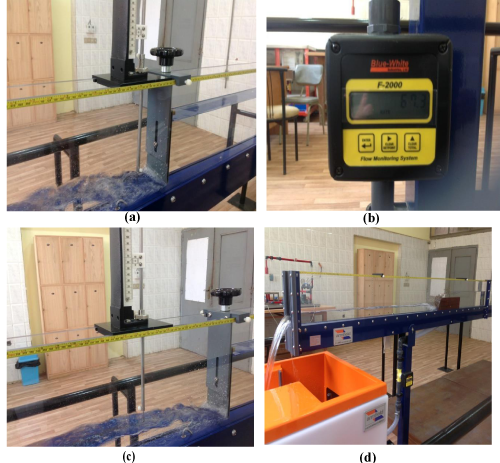
Figure 3: (a) Measured upstream conjugate depth of hydraulic jump, (b) Measured discharge through digital flow meter, (c) Measured downstream conjugate depth of hydraulic jump and (d) different locations of hydraulic jump.
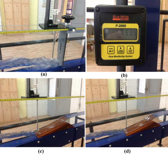
Figure 4: (a) Measured critical depth of the hydraulic jump, (b) Measured discharge through digital flow meter, and (c) Measured weir level and (d) Measured water level at upstream conjugate depth of hydraulic jump.
CONCLUSION
A hydraulic jump experiment was accomplished in a rectangular open channel flume under the influence of various flow structures. Several experimental runs were accomplished to obtain Y2 by measuring Y1 and Q using different flow structures and various gate openings. The measured values of Y2 disagree with the simulated results of former equations. Also, the measured Y2 varies by varying the flow structure for the same Y1 and Q that reveals that the former equations of hydraulic jump should be modified to show the impact of shear force due to friction between hydraulic jump and bed of water canals. The change in downstream depth is relevant to the existence of shear force resistance obtained by the flow structure in water canals that can lead to bed scouring. Regarding open channel flume, the impact of shear force may owe to the friction between hydraulic jump flow and wall sides. Also, the experimental runs revealed that upstream Froude number increases from 1.4 to 2.6 by increasing downstream depth from 5 cm to 6 cm at constant discharge and gate opening where the jump returns back to the gate owing to the decline in specific force vena contraction.
ACKNOWLEDGEMENTS
The author acknowledges the assistance provided by Institute of Aviation Engineering and Technology in supplying Hydraulic laboratory with Armfield open channel flume imported from England in 2015.
REFERENCES
- Lau YL, Liu D. Effect of flow rate on biofilm accumulation in open channels. Water Research. 1993; 27: 355-360. Ref.: https://goo.gl/g66Gxj
- Sofialidis D, Prinos P. Turbulent flow in open channels with smooth and rough flood plains. J Hydraulic Res. 1999; 37: 615-640. Ref.: https://goo.gl/sJuWW5
- Chanson H. Minimum Specific Energy and Critical Flow Conditions in Open Channels. J Irrigation Drainage Eng. 2006; 132: 498-502.
- Bilgil A, Altun H. Investigation of flow resistance in smooth open channels using artificial neural networks. Flow Measurement and Instrumentation. 2008; 19: 404-408. Ref.: https://goo.gl/V2XZ5T
- Song CG, Seo IW, Kim YD. Analysis of secondary current effect in the modeling of shallow flow in open channels. Advances in Water Resources. 2012; 41: 29-48. Ref.: https://goo.gl/2d998M
- Hussain A, Ahmad Z, Ojha CSP. Analysis of flow through lateral rectangular orifices in open channels. Flow Measurement and Instrumentation. 2014; 36: 32-35. Ref.: https://goo.gl/KjpNi5
- Kim Y, Gyewoon Choi G, Park H, Byeon S. Hydraulic Jump and Energy Dissipation with Sluice Gate. Water. 2015; 7: 5115-5135. Ref.: https://goo.gl/QeMC6o
- Shamloo H, Pirzadeh B. Analysis of roughness density and flow submergence effects on turbulence flow characteristics in open channels using a large eddy simulation. Applied Mathematical Modelling. 2015; 39: 1074-1086. Ref.: https://goo.gl/jq2b5a
- Gandhi BK, Verma HK, Abraham B. Mathematical modeling and simulation of flow velocity profile for rectangular open channels. ISH Journal of Hydraulic Engineering. 2016; 22: 1-11. Ref.: https://goo.gl/4hRSg6
- Sadeque MA, Rajaratnam N, Loewen MR. Effects of Bed Roughness on Flow around Bed-Mounted Cylinders in Open Channels. Journal of Engineering Mechanics. 2009; 135: 100-110. Ref.: https://goo.gl/uFg4o7
- Burger J, Haldenwang R, Alderman N. Friction factor-Reynolds number relationship for laminar flow of non-Newtonian fluids in open channels of different cross-sectional shapes. Chemical Engineering Science. 2010; 65: 3549-3556. Ref.: https://goo.gl/BxYL7T
- Blanckaert K, Duarte A, Schleiss AJ. Influence of shallowness, bank inclination and bank roughness on the variability of flow patterns and boundary shear stress due to secondary currents in straight open-channels. Advances in Water Resources. 2010; 33: 1062-1074. Ref.: https://goo.gl/Lt9Vae
- D’Oria M, Tanda MG. Reverse flow routing in open channels: A Bayesian Geostatistical Approach. Journal of Hydrology. 2012; 460-461: 130-135. Ref.: https://goo.gl/qjERvG
- Kim YJ. Energy Dissipation Effect of the Downstream at Under Flow Movable Weir. Ph.D. Thesis, Incheon National University, Incheon, Korea. 2013.
- Ba Tuyen N, Cheng N. Flow Resistance in Smooth Rectangular Open Channels with Low Aspect Ratios. Journal of Hydraulic Engineering 2012; 138: 817-821. Ref.: https://goo.gl/PT72pR
- Abbaspour A, Parvini S, Dalir HA. Effect of buried plates on scour profiles downstream of hydraulic jump in open channels with horizontal and reverse bed slopes. Water Science and Engineering. 2016; 9: 329-335. Ref.: https://goo.gl/9p9Fnm